Main speed reducing device having dynamic branch off structure

A main reducer and power splitting technology, which is applied in the direction of transmission, gear transmission, differential transmission, etc., can solve the problems of limiting the load capacity of the differential gear, not conducive to reducing the weight of the main reducer, and large frictional torque , to achieve the effect of compact structure, reducing the cost of the axle and improving the bearing capacity

Inactive Publication Date: 2009-02-18
BEIJING JIAOTONG UNIV
View PDF5 Cites 0 Cited by
  • Summary
  • Abstract
  • Description
  • Claims
  • Application Information

AI Technical Summary

Problems solved by technology

The design including the flange and the relatively thick differential case are not conducive to reducing the weight of the final drive, but also limit the load-carrying capacity of the differential gears arranged inside the differential case
The axial force borne on the differential case is finally transmitted to the final drive case through a pair of tapered roller bearings installed in the differential case. The friction of the tapered roller bearings under large axial loads High torque, low efficiency

Method used


Image

  • Main speed reducing device having dynamic branch off structure
  • Main speed reducing device having dynamic branch off structure
  • Main speed reducing device having dynamic branch off structure

Examples


Embodiment Construction

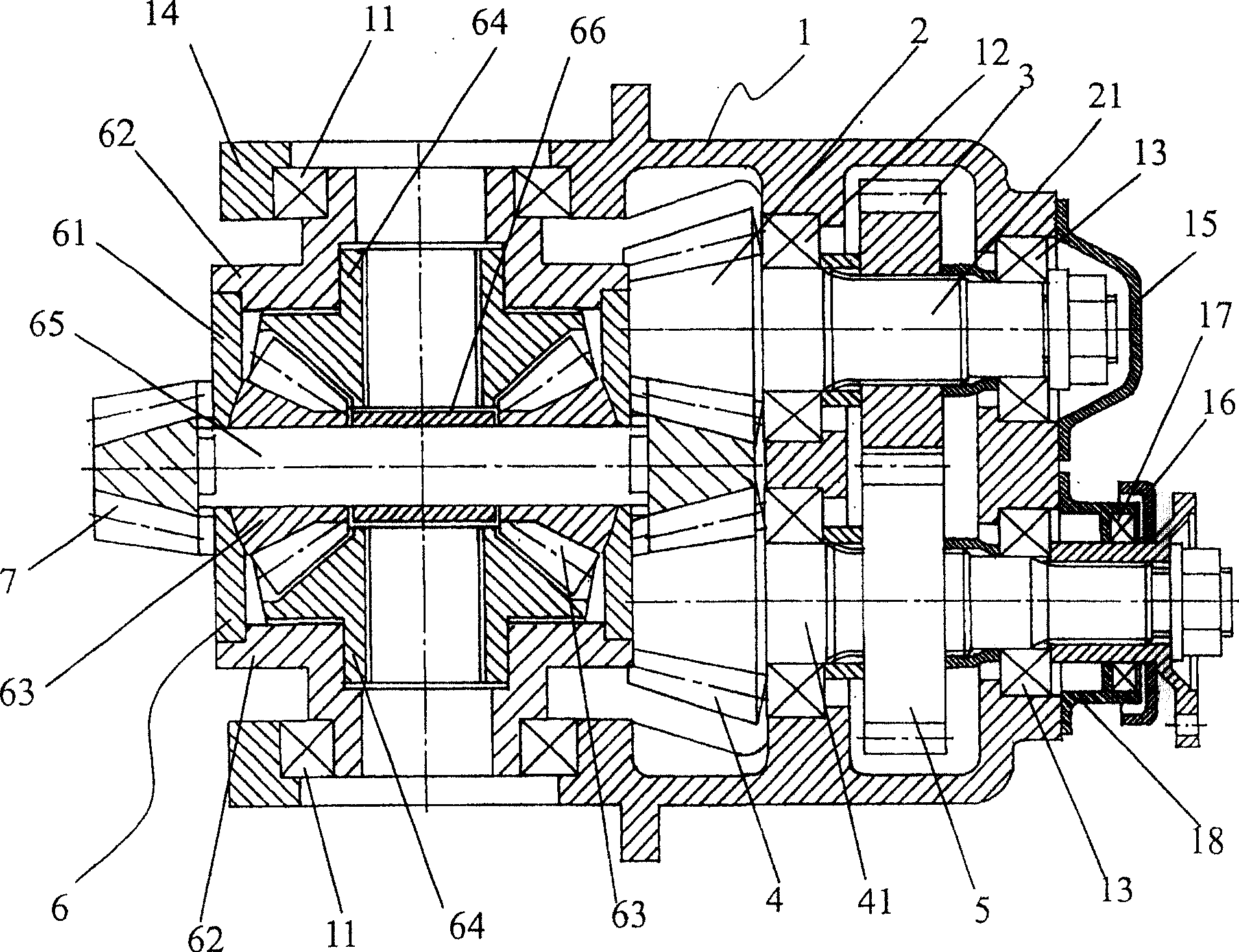
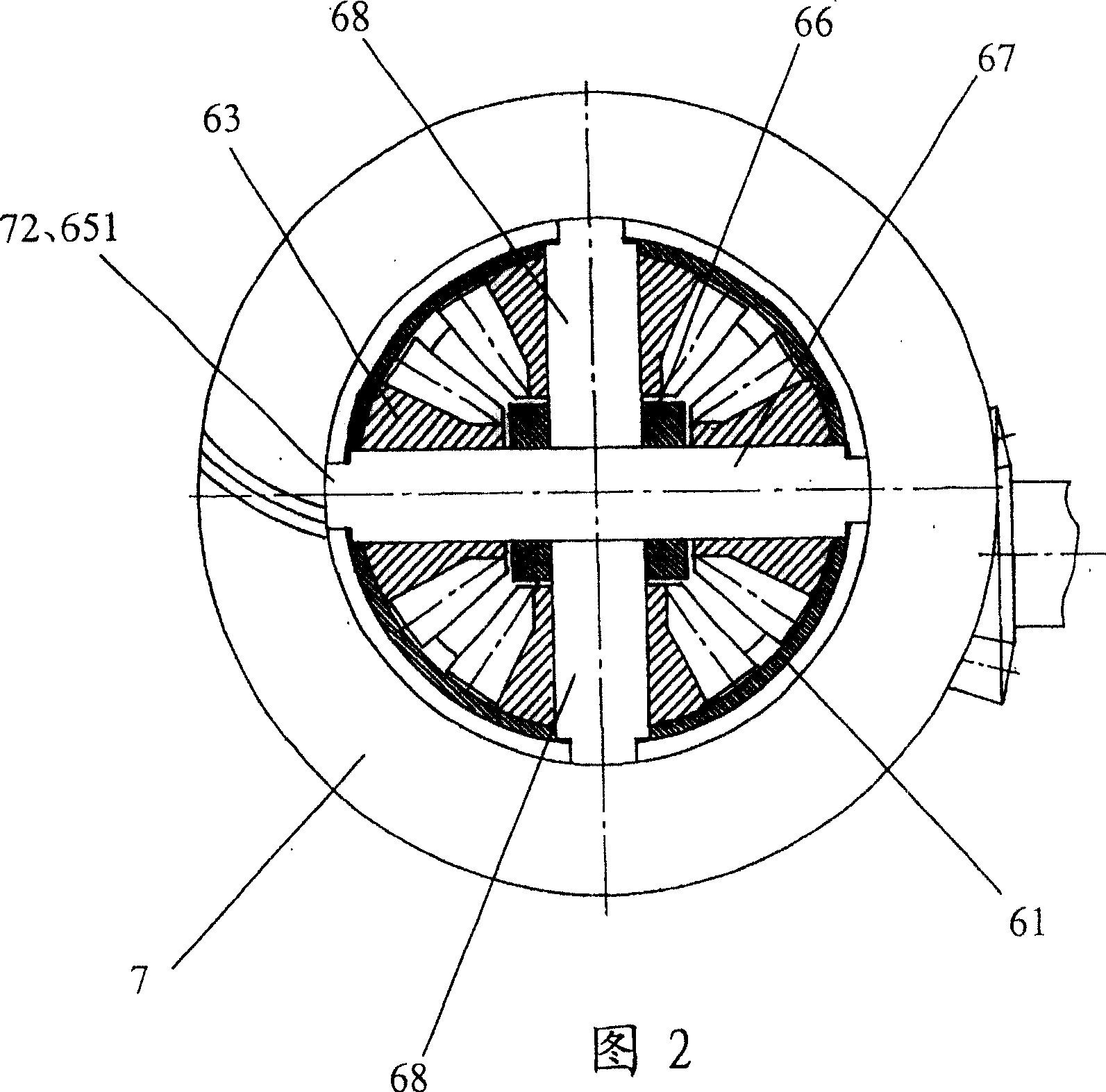
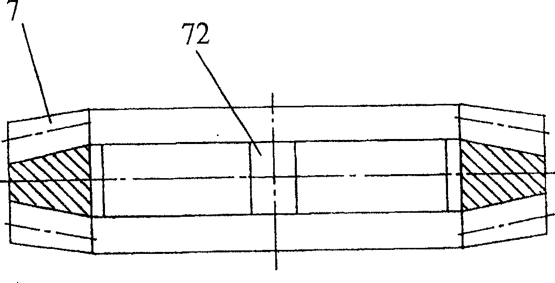
[0032] Such as figure 1 As shown, the final drive with a power split structure of the present invention at least includes a final drive housing 1, a differential assembly 6 arranged on the final drive housing 1, and a differential assembly The upper driven gear 7 and the two driving gears 2 and 4 arranged on the main reducer housing 1 and meshing with the driven gear 7. For the convenience of description, taking the main reducer used for the rear drive axle as an example, the driving gear 2 and 4 become the left driving gear 2 and the right driving gear 4 respectively. Such as figure 1 , image 3 As shown, the two end faces of the driven gear 7 of the present invention are formed with teeth with the same number of teeth. The left driving gear 2 and the right driving gear 4 have the same number of teeth, and they mesh with the driving gears on both sides of the driven gear 7, respectively. The gear shaft 21 of the left driving gear 2 is provided with a left power splitting cylind...


PUM


Abstract

This invention relates to a kind of split-power final reduction gear comprises a final driving casing (1), two driving pinions (2) and (4), a pair of split-power cylindrical gears (3) and (5), heavy-duty differential assembly (6) and a driven gear (7). Input power applies to either driving pinion (2) or (4), then half of the input power is shifted to the other driving pinion through split-power cylindrical gears (3) and (5). The driven gear (7) is supported on the differential assembly (6), and same number of teeth are machined in both sides of it. The driven gear engages with both driving pinions, concentrates the power from two transmission branches to itself and in tern transfers the power to differential assembly. With present invention, hub reductors can be eliminated while ground clearance were kept unreduced, thus the cost of driving axles is cut down, fuel consumption and noise are decreased.

Description

Technical field [0001] The invention relates to a final reducer suitable for a wheeled vehicle drive axle, in particular to a final reducer with a power split structure. Background technique [0002] In order to improve the off-road performance and passing ability of vehicles, many off-road vehicles, off-road load vehicles and engineering vehicles require a large ground clearance. In many cases, the ground clearance of the vehicle mainly depends on the diameter and the driving wheel. The diameter of the main reducer. In order to meet the required output torque, the diameter of the passive gear is relatively large, and it is difficult to meet the requirements of the ground clearance at the same time. For this reason, many construction vehicles have to adopt wheel rims. The double-stage reduction mechanism of the reducer. The double-stage reduction axle adopts a smaller transmission ratio in the main reduction stage, which reduces the output torque on the driven gear, thereby reduc...

Claims


Application Information

Patent Timeline
Patent Type & Authority Patents(China)
IPC IPC(8): F16H1/20F16H48/06F16H48/08F16H48/38
CPCF16H2048/385F16H1/22F16H2048/085F16H48/08
Inventor 姜虹王小椿
Owner BEIJING JIAOTONG UNIV
Why Eureka
Try Eureka