Receiving machine support seat with adjustable flatness

A technology for receivers and support seats, which is applied in the direction of machines/brackets, supporting machines, mechanical equipment, etc., can solve the problem that the support seat is difficult to maintain an accurate horizontal state, and achieve the effect of simple structure

Inactive Publication Date: 2015-04-29
GUIZOU QIANCHENGTIANLI INTELLIGENT TECH
View PDF5 Cites 0 Cited by
  • Summary
  • Abstract
  • Description
  • Claims
  • Application Information

AI Technical Summary

Problems solved by technology

[0003] The Beidou GPS dual-mode receiver is generally installed and fixed on a stable installa

Method used


Image

  • Receiving machine support seat with adjustable flatness

Examples


Embodiment Construction

[0014] The present invention will be described in detail below with reference to the accompanying drawings and examples.

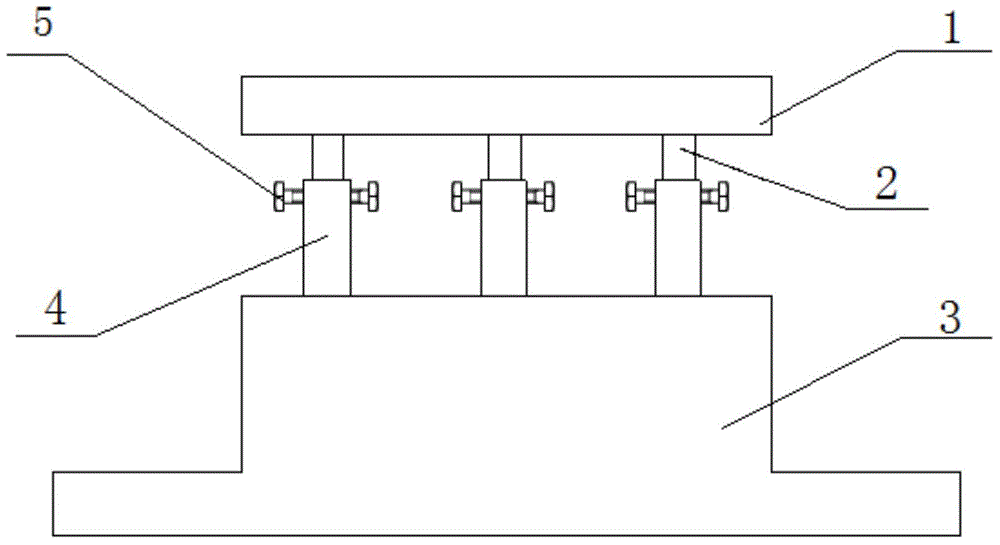
[0015] as attached figure 1 As shown, the present invention provides a receiver support seat with adjustable flatness, including an upper flange 1, a base 3, a telescopic rod 2, a telescopic sleeve 4 and a locking bolt 5;

[0016] Both the bottom surface and the upper surface of the base 3 are plane;

[0017] Its overall connection relationship is: one end of the telescopic sleeve 4 is fixedly connected to the upper surface of the base 3, one end of the telescopic rod 2 is fixedly connected to the bottom surface of the upper flange 1, and the telescopic rod 2 and the telescopic sleeve 4 are both Three, on the respective connecting surfaces, are centrally symmetrically distributed, and the other end of the telescopic rod 2 stretches into the telescopic sleeve 4 from the other end of the telescopic sleeve 4, and the outer circumferential surface of the tele...


PUM


Abstract

The invention discloses a receiving machine support seat with adjustable flatness, which comprises an upper flange, a base, telescopic rods, telescopic sleeves and locking bolts, wherein the bottom surface and the upper surface of the base are respectively a plane; one end of each telescopic sleeve is fixedly connected with the upper surface of the base; one end of each telescopic rod is fixedly connected with the bottom surface of the upper flange; three telescopic rods and three telescopic sleeves are arranged and are distributed on respective connecting surfaces in a central symmetry mode; the other ends of the telescopic rods stretch into the telescopic sleeves from the other ends of the telescopic sleeves; the outer circumferential surface of each telescopic rod is in sliding fit to the inner circumferential surface of the corresponding telescopic sleeve; the locking bolts penetrate through sleeve walls to lock the telescopic rods along the radial directions of the telescopic sleeves. According to the receiving machine support seat, the levelness of the support seat can be conveniently adjusted, and a receiving machine is guaranteed to be at the best working condition.

Description


Claims


Application Information

Patent Timeline
Owner GUIZOU QIANCHENGTIANLI INTELLIGENT TECH
Why Eureka
Try Eureka