High-pressure top-mounted magnetic flap level gauge float

A magnetic flap liquid level and top-loading technology, which is applied in the direction of buoy liquid level indicators, etc., can solve the problems of liquid level gauge failure, inconvenience, etc., and achieve ideal results

Inactive Publication Date: 2015-04-29
广西梧州日成林产化工股份有限公司
View PDF5 Cites 2 Cited by
  • Summary
  • Abstract
  • Description
  • Claims
  • Application Information

AI Technical Summary

Problems solved by technology

[0005] The problem to be solved by the present invention is to provide a high-voltage top-mounted magnetic flap liquid level gauge float to solve the problem that the existing high-pressure top-mounted magnetic flap liquid level gauge float easily causes the liquid level gauge to fail and is inconvenient to use.

Method used


Image

  • High-pressure top-mounted magnetic flap level gauge float

Examples


Embodiment Construction

[0012] Embodiments of the present invention are described in further detail below in conjunction with the accompanying drawings:

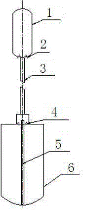
[0013] Such as figure 1 The high-voltage top-mounted magnetic flap liquid level gauge float shown above includes a magnet 1 with a through hole 2 on the upper part, where the magnet 1 is a magnetic ball, connected to the connecting rod 3 at the bottom of the magnet 2, and the lower end of the connecting rod 3 is installed There is a buoy 6, inside the buoy 6 there is a discharge pipe 5 that runs through the buoy 6, the upper end of the buoy 6 is provided with a hole 4, and the air channel formed by the hole 4 at the upper end of the buoy 6 communicates with the upper end of the discharge pipe 5, through the hole 4 and discharge pipe 5 to discharge liquid and balance pressure, so that the liquid level gauge can work under high pressure. The middle of the upper end of the buoy 6 is provided with a circular raised portion, and there are a plurality o...


PUM


Abstract

The invention discloses a high-pressure top-mounted magnetic flap level gauge float. The high-pressure top-mounted magnetic flap level gauge float comprises a magnetic body, the upper part of which is provided with a through hole, and a connecting rod connected to the bottom of the magnetic body, wherein a float bowl is arranged on the lower end of the connecting rod; a liquid drainage pipe longitudinally penetrating the float bowl is arranged in the float bowl; the upper end of the float bowl is provided with a hole; an air channel is formed in the upper end of the float blow through the hole and is communicated with the upper end of the liquid drainage pipe. Compared with the prior art, the high-pressure top-mounted magnetic flap level gauge float can be used for solving the problem that an existing high-pressure top-mounted flap level gauge float is easy to cause failure of the level gauge and inconvenient to use.

Description

technical field [0001] The invention relates to the technical field of instrument equipment manufacturing, in particular to a liquid level gauge float used for liquid level detection of high-temperature liquid and normal-temperature solid substances such as rosin and asphalt. Background technique [0002] The existing top-mounted magnetic flap (column) liquid level gauge includes the liquid level gauge body formed by the upper and lower conduits, and the flap box composed of red and white two-color magnetic small flaps is arranged at the lower end of the body, and the upper band passes The magnet of the hole and the float formed by the lower buoy connected by the connecting rod, as well as the liquid level transmitter and so on. Its working principle is as follows: the float in the container floats up and down with the change of the liquid level, and the magnetic ball moves up and down in the upper conduit through the connecting rod, prompting the flap outside the body to tu...

Claims


Application Information

Patent Timeline
Patent Type & Authority Applications(China)
IPC IPC(8): G01F23/76
Inventor 聂雄建侯文彪黄卫赵桂山
Owner 广西梧州日成林产化工股份有限公司
Why Eureka
Try Eureka