Seismic imaging method and device for direct imaging from undulating surface

A technology of undulating surface and imaging method, which is applied in the direction of seismic signal processing, etc., can solve the problem that the application effect of refracted wave static correction cannot be guaranteed, and achieve the effect of objective and true processing results and avoid structural distortion

Inactive Publication Date: 2015-04-29
BGP OF CHINA NAT GASOLINEEUM CORP +1
View PDF5 Cites 15 Cited by
  • Summary
  • Abstract
  • Description
  • Claims
  • Application Information

AI Technical Summary

Problems solved by technology

However, the premise of the application of this method is that there must be a relatively stable low speed drop zone.
Generally, there is no low speed drop zone or a relatively stable low speed drop zone in mountainous areas, so the application effect of refracted wave static correction cannot be guaranteed.

Method used


Image

  • Seismic imaging method and device for direct imaging from undulating surface
  • Seismic imaging method and device for direct imaging from undulating surface
  • Seismic imaging method and device for direct imaging from undulating surface

Examples


Embodiment Construction

[0039] Embodiments of the present invention will be further described in detail below in conjunction with the accompanying drawings.

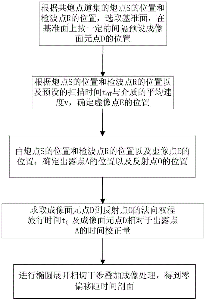
[0040] Such as figure 1 As shown, a seismic imaging method for direct imaging from undulating surfaces includes the following steps:

[0041]Step 1. According to the position of the shot point S and the position of the receiver point R of the common shot point gather, select the datum plane, divide the position and size of the imaging bin on the datum plane according to a certain interval, and preset the imaging bin point D The position of , that is, the designated imaging position on the same reference plane;

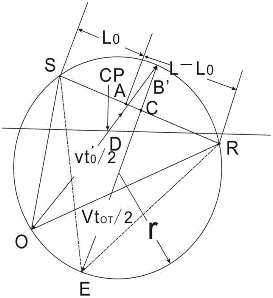
[0042] Step 2. According to the position of the shot point S, the position of the receiver point R and the preset scanning time t 0T and the average velocity v of the medium to determine the position of the virtual image point E;

[0043] Step 3: Determine the position of the pole B' from the position of the shot point S, the positio...


PUM


Abstract

The invention provides a seismic imaging method and device for direct imaging from an undulating surface, through which an imaging section can be directly obtained from a common shot point gather and the obtained processing result is more objective and real. The imaging method comprises the following steps: 1, according to a position of a shot point and a position of a detection point of the common shot point gather, selecting a datum plane and presetting a position of an imaging plane original point at certain interval on the datum plane; 2, determining a position of a virtual image point according to the position of the shot point, the position of the detection point, default scanning time and average velocity of a medium; 3, determining a position of a dew point and a position of a reflection point where the dew point is reflected to the detection point through the shot point by combining the position of the imaging plane original point based on positions of the shot point, the detection point and the virtual image point; 4, calculating normal direction round trip traveling time from the imaging plane original point to the reflection point and time correcting value of the imaging plane original point compared with the exposure point; 5, performing ellipse expansion tangent interference superposition imaging processing to obtain a zero-offset time section.

Description

technical field [0001] The invention relates to the technical field of seismic data processing, in particular to a seismic imaging method and device for direct imaging from undulating surfaces. Background technique [0002] With the continuous development of seismic exploration technology, the requirements for the processing technology of the collected seismic exploration data are also getting higher and higher. In actual seismic data processing, reflection seismic data processing technology in seismic exploration data involves the category of stacking imaging technology in the process of seismic data processing. Most of the existing reflection seismic data processing and imaging methods require the shot point and the receiver point to be located on the same horizontal plane, and assume that the underground medium is layered and uniform. With the deepening of exploration work, the surface geological and seismic conditions of the exploration target and the exploration area a...

Claims


Application Information

Patent Timeline
Patent Type & Authority Applications(China)
IPC IPC(8): G01V1/28
Inventor 周青春谢桂生孙庚文康德拉什科夫
Owner BGP OF CHINA NAT GASOLINEEUM CORP
Why Eureka
Try Eureka