Door interlock device for transformer room of vacuum circuit breaker

A vacuum circuit breaker and interlocking device technology, which is applied to high-voltage air circuit breakers, switchgear, grounding devices of switchgear, etc., and can solve problems such as dangerous environments for users

Active Publication Date: 2015-04-29
LSIS CO LTD
View PDF4 Cites 5 Cited by
  • Summary
  • Abstract
  • Description
  • Claims
  • Application Information

AI Technical Summary

Problems solved by technology

However, when the door 5 of the power transformer unit is opened without the earthing switch being closed, a serious problem may arise, namely putting the user in a dangerous environment due to the residual voltage left in the power transformer room 7

Method used


Image

  • Door interlock device for transformer room of vacuum circuit breaker
  • Door interlock device for transformer room of vacuum circuit breaker
  • Door interlock device for transformer room of vacuum circuit breaker

Examples


Embodiment Construction

[0031] A preferred embodiment of a door interlock device for a power transformer room according to an embodiment of the present invention will be described in detail below with reference to the accompanying drawings.

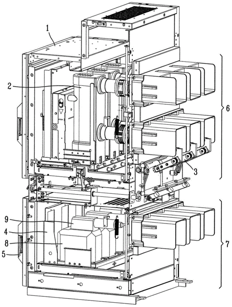
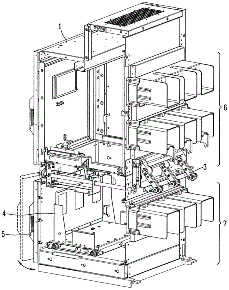
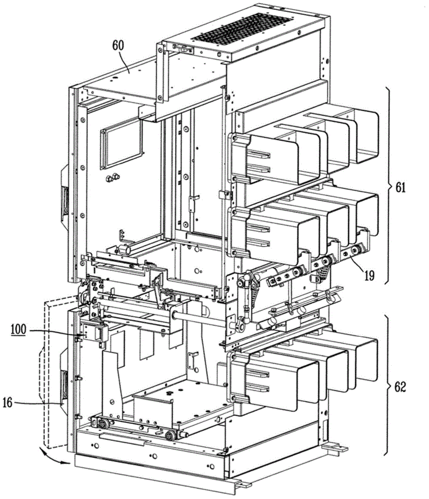
[0032] boxes Figure 4 is showing image 3 A partial perspective view of the grounding switch of the switch box when it is disconnected, Figure 5 is showing Figure 4 A detailed perspective view of the interlocking components of the, Figure 6 yes Figure 5 The exploded perspective view of Figure 7 is showing Figure 4 A detailed perspective view of the door of , and Figure 8 is a perspective view showing a door interlock device for a power transformer room according to an embodiment of the present invention in which a grounding switch is closed.

[0033] As shown in the figure, in a switch box provided with a circuit breaker room and a power transformer room and in which a grounding switch 19 is arranged to be movable to a closed position and an open ...


PUM


Abstract

A door interlock device for a power transformer room in a vacuum circuit breaker includes a cam disposed on a shaft of a ground switch, a supporter disposed on a side plate of a power transformer room, a shaft disposed at the supporter to be slidable and having one end contacting the cam to be upward and downward movable, a spring disposed within the supporter to provide an upward elastic force to the shaft, and an interlock plate disposed at one side of the power transformer room door and configured to be in contact with the shaft, wherein the transformer room door is not allowed to move when the interlock plate is restricted by the shaft, but the power transformer room door is allowed to move when the interlock plate is released from the restriction of the shaft. The door interlock device for a power transformer room is capable of securing the safety of a user by providing the door to be opened only in a ground condition.

Description

technical field [0001] The present invention relates to a door interlocking device for a transformer room of a vacuum circuit breaker, and more particularly to a transformer room for a vacuum circuit breaker which is constructed so that the door of the transformer room can be opened by a user only when the grounding switch is in a closed state door interlock device. Background technique [0002] Typically, vacuum circuit breakers are placed in switchboards, along with various other electrical devices, to operate or control the operation of power line systems and electric motors in power plants or substations. Further, the vacuum circuit breaker is generally arranged in a support in an insertable and extractable manner, and the support is fixed to the switchboard. [0003] There are running (operating) positions and test positions on the switchboard, the former is the position where the main line and load terminals of the vacuum circuit breaker are connected to the main line...

Claims


Application Information

Patent Timeline
Patent Type & Authority Applications(China)
IPC IPC(8): H01H33/48H01H33/66
CPCH02B11/133H02B11/28H01H9/22H01H31/06Y10T292/1016E05B49/00E05B49/002H01H9/24E05B65/00
Inventor 金钟斗安吉荣梁承必
Owner LSIS CO LTD
Why Eureka
Try Eureka