Flashlight power adjusting method and terminal

An adjustment method and flash technology, applied in the field of electronics, can solve the problems of energy consumption, excessive exposure, and the brightness of the photographed object does not reach the expected value, and achieve the effect of saving energy

Active Publication Date: 2015-04-29
GUANGDONG OPPO MOBILE TELECOMM CORP LTD
View PDF2 Cites 37 Cited by
  • Summary
  • Abstract
  • Description
  • Claims
  • Application Information

AI Technical Summary

Problems solved by technology

[0003] At present, when the flashlight in the terminal is shooting, the brightness of the flashlight is generally fixed, which will cause the brightness of the object in the digital image to vary due to the failure to properly adjust the flashlight when the subject is far away from the digital photography device. meet expectations
In addition, when the subject is close to the digital photography device, the subject is overexposed and energy is consumed due to the failure to adjust the flash properly.

Method used


Image

  • Flashlight power adjusting method and terminal
  • Flashlight power adjusting method and terminal
  • Flashlight power adjusting method and terminal

Examples


no. 1 example

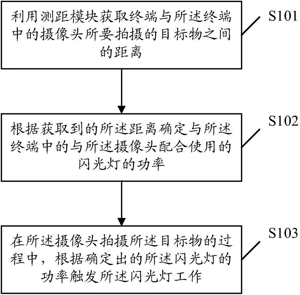
[0031] See figure 1 , which provides a flow chart of the first embodiment of a method for determining flashlight power in an embodiment of the present invention. The method includes the following steps:

[0032] S101. Acquire the distance between the terminal and the object to be photographed by the camera in the terminal by using the ranging module.

[0033] Specifically, the distance between the terminal and the object to be photographed by the camera in the terminal is obtained by using the ranging module, wherein the ranging module includes: a laser ranging module or a dual-camera phase ranging module. The principle of laser ranging: 1) Pulse method: the laser emitted by the rangefinder is reflected by the target and then received by the rangefinder. The rangefinder records the time of the laser back and forth at the same time. Therefore, according to the displacement formula s=v t , so that the distance between the photographed target and the terminal can be obtained as...

no. 2 example

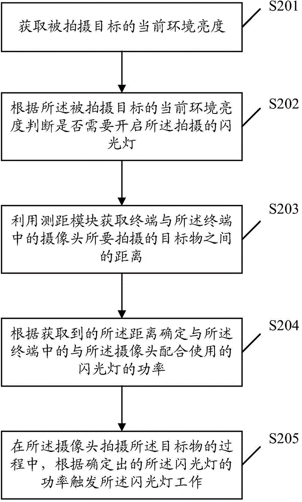
[0051] See figure 2 , which provides a flowchart of the second embodiment of a method for determining the power of a flashlight according to the embodiment of the present invention. The method includes the following steps:

[0052] S201. Acquire the current ambient brightness of the object to be photographed.

[0053] Specifically, before using the ranging module to obtain the distance between the terminal and the object to be photographed by the camera in the terminal, obtaining the current ambient brightness of the photographed object includes: collecting an image of the photographed object, The current ambient brightness of the photographed target is obtained by analyzing the brightness of the image.

[0054] S202. Determine whether to turn on the photographing flashlight according to the current ambient brightness of the subject to be photographed.

[0055] Specifically, it is judged whether the above-mentioned current ambient brightness luma is less than 40 according ...


PUM


Abstract

The embodiment of the invention relates to the field of electronic technologies, and discloses a flashlight power adjusting method. The method includes the steps that the distance between a terminal and a target object to be shot by a camera in the terminal is obtained through a distance measuring module; the power of a flashlight used in match with the camera in the terminal is determined according to the obtained distance; in the process that the camera shoots the target object, the flashlight is triggered to work according to the determined power of the flashlight. The embodiment of the invention further provides the terminal. By means of the flashlight power adjusting method and terminal, the power of the flashlight can be adjusted automatically according to the distance between the object to be shot and the shooting device, accordingly the brightness of the flashlight is adjusted, and thus energy is saved.

Description

technical field [0001] The present invention relates to the field of electronic technology, in particular to a method for adjusting the power of a flashlight and a terminal. Background technique [0002] In general digital photographic devices, such as digital cameras, flashlights are photosensitive photographic accessories, and are mostly used for instant lighting in darker light situations, and are also used for local supplementary light for photographed objects in brighter light situations. When the object to be photographed is in a dark environment, the digital photography device activates the flashlight while shooting, so that the digital photography device can use the strong light from the flashlight to make the brightness of the object to be photographed in the digital image reach a desired value. The flashing process of the digital photography device is as follows: the digital photography device obtains the brightness of the current external environment before flashi...

Claims


Application Information

Patent Timeline
Patent Type & Authority Applications(China)
IPC IPC(8): H04N5/235H04N5/232
Inventor 孙剑波
Owner GUANGDONG OPPO MOBILE TELECOMM CORP LTD
Why Eureka
Try Eureka