Vibration motor

A vibration motor and drive mechanism technology, applied in the direction of connection with the control/drive circuit, electrical components, electromechanical devices, etc., can solve the problem that vibration cannot be transmitted

Active Publication Date: 2015-05-13
东莞市富泰电机有限公司
View PDF6 Cites 3 Cited by
  • Summary
  • Abstract
  • Description
  • Claims
  • Application Information

AI Technical Summary

Problems solved by technology

At this time, a contradiction arises: that is, because the natural frequency of the output shaft of the existing personal care appliance vibration motor is fixed at the time of design (determined by the hardness and quality of the output shaft material), the output of the coil The frequency is adjusted at any time according to the needs of the user. When switching between different gears, it is difficult to make the output frequency of the coil consistent with the natural frequency of the output shaft. At this time, the vibration will not be fully transmitted to the required parts.

Method used


Image

  • Vibration motor
  • Vibration motor
  • Vibration motor

Examples


Embodiment Construction

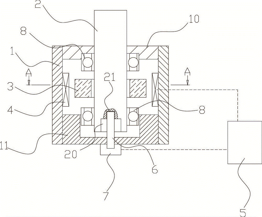
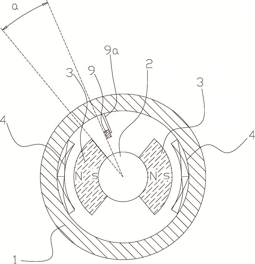
[0012] The present invention will be described in further detail below in conjunction with accompanying drawing and specific embodiment: see Figure 1 to Figure 2 As shown, the vibration motor includes a housing 1, and the housing 1 includes an upper end cover 10 and a lower end cover 11, and an output shaft 2 is rotated in the housing 1, and in the upper end cover 10 and the lower end cover 11 A bearing 8 for supporting the output shaft 2 is provided, and two oppositely placed coils 4 are provided on the side wall of the housing 1, and AC power is passed through the coils 4 so that an alternating current is formed between the coils. The magnetic field also includes a gear switch 5 for controlling the frequency of the AC power supply, and an armature component 3 corresponding to the coil 4 is fixedly arranged on the output shaft 2 . There is a gap between the armature component 3 and the coil 4, so that the output shaft 2 can swing back and forth at a specific angle within the...


PUM


Abstract

The invention discloses a vibration motor. The vibration motor comprises a housing, and further comprises a gear switch used for controlling the frequency of an alternating-current power supply, and an elastic insertion piece, wherein an output shaft is rotationally arranged in the housing; two opposite coils are arranged on a side wall of the housing; an armature part in response to the coils is fixedly arranged on the output shaft; a slot is formed in the bottom of the output shaft; an insertion slot allowing the elastic insertion piece to insert is formed in a bottom end of the slot; a drive mechanism pushing the elastic insertion piece is arranged at one end of the elastic insertion piece. Compared with the prior art, the slot allowing the elastic insertion piece to insert is formed in the bottom of the output shaft and the drive mechanism pushing a spring leaf is arranged, so that when the gear switch performs switching among gears at different vibration frequencies, the spring leaf is inserted into the slot of the output shaft through the drive mechanism to change an elastic deformation coefficient of the spring leaf, and the coil output frequency can be guaranteed to be the same as the frequency of the output shaft of the vibration motor when a maintenance tool is switched among the gears at different frequencies.

Description

technical field [0001] The invention belongs to the field of motors, and more specifically relates to a vibration motor. Background technique [0002] Vibration motors are motors commonly used in personal care appliances, such as electric toothbrushes, electric face washers, etc., all have vibration motors inside, and the output shaft of the vibration motor is connected to the brush head to transfer the vibration of the output shaft of the vibration motor to the brush head. site transfer. The vibration motor of the existing vibration motor includes a housing, in which there are two oppositely placed coils, an AC power supply is passed through the coils, and a gear switch for controlling the frequency of the AC power supply is also included. The output shaft is rotatably arranged inside the housing, and armatures are arranged at both ends of the output shaft, and the armature responds to the change of the magnetic field in the coil so that the output shaft moves along the sh...

Claims


Application Information

Patent Timeline
Patent Type & Authority Applications(China)
IPC IPC(8): H02K7/00H02K11/00H02K11/33
CPCH02K33/02
Inventor 梁荣
Owner 东莞市富泰电机有限公司
Why Eureka
Try Eureka