
Permanent magnet retarder

A retarder, permanent magnet technology, applied in the field of permanent magnet retarder, can solve the problem of unsatisfactory maximum braking torque, etc., and achieve the effect of easy popularization, strong practicability, and improved work stability

Active Publication Date: 2017-11-21
JIANGSU UNIV OF TECH
View PDF5 Cites 0 Cited by
  • Summary
  • Abstract
  • Description
  • Claims
  • Application Information

AI Technical Summary

Problems solved by technology

The above invention can realize the continuous adjustment of the braking torque of the permanent magnet retarder, but the maximum braking torque is still not ideal

Method used


Image

  • Permanent magnet retarder
  • Permanent magnet retarder
  • Permanent magnet retarder

Examples


Embodiment 1

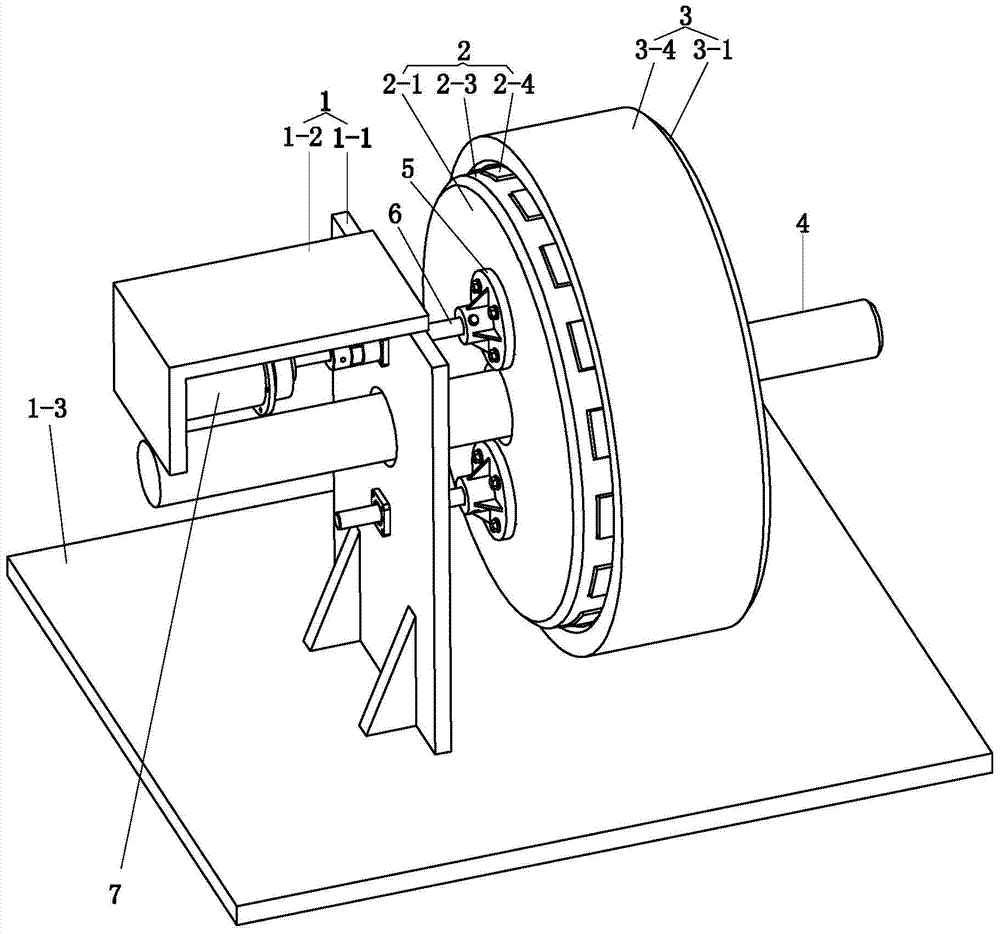
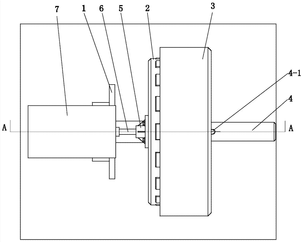
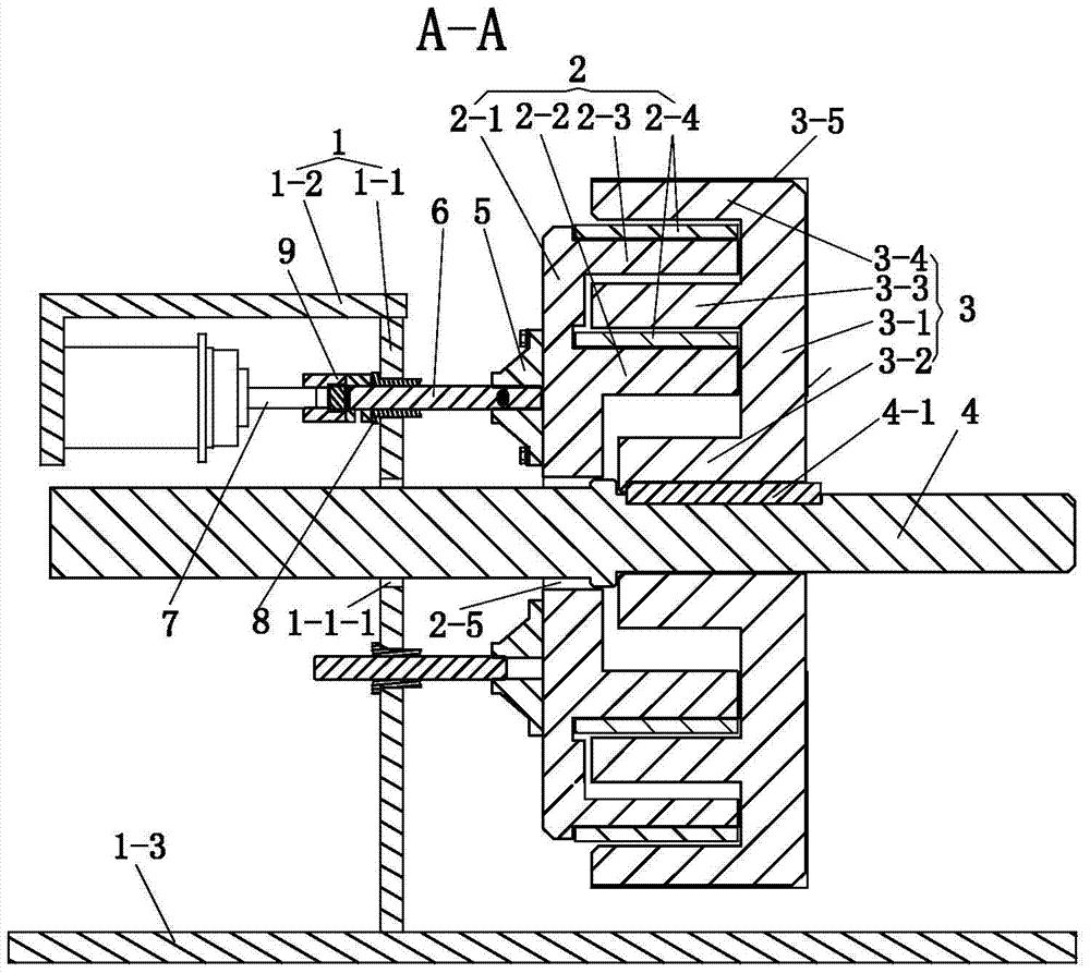
[0014] see Figure 1 to Figure 5 , This embodiment has a bracket 1, a stator 2, a rotor drum 3 and a transmission shaft 4.

[0015] The bracket 1 includes a bottom plate 1-3, a vertical plate 1-1 and a top plate 1-2. The vertical plate 1-1 is fixed on the bottom plate 1-3, and the top plate 1-2 is fixed on the vertical plate 1-1.

[0016] The stator 2 has an end plate 2-1, an inner ring cage 2-2 and an outer ring cage 2-3 fixed on the end plate 2-1 and are coaxial, the inner ring cage 2-2 and the outer ring cage 2-2 Permanent magnet blocks 2-4 are distributed on the ring cage 2-3.

[0017] The rotor drum 3 has an end plate 3-1, a shaft sleeve 3-2, an inner ring body 3-3, and an outer body 3-4 fixed on the end plate 3-1 and being coaxial. The outer shell 3-1 of the rotor drum 3 is provided with heat dissipation fins 3-5.

[0018] The transmission shaft 4 passes through the shaft sleeve 3-2 of the rotor drum 3, the shaft hole 2-5 on the stator 2 and the through hole of the vertical pl...


PUM


Abstract

A permanent magnet retarder, with a bracket, a stator, a rotor drum and a drive shaft; the stator has an end plate and an inner ring cage and an outer ring cage fixed on the end plate, and the rotor drum has an end plate And the shaft sleeve, inner ring body and outer casing fixed on the end plate; the transmission shaft is fixedly connected with the shaft sleeve of the rotor drum, and two symmetrically distributed fixing seats are fixed on the outer surface of the end plate of the stator, each fixing seat A push-pull rod is connected to the top of the bracket, and an electric push rod is fixed on one of the fixed seats on the top plate of the bracket, and the electric push rod is connected with the corresponding push-pull rod; The outer ring cage of the stator can be inserted into the annular cavity between the inner ring body and the outer shell of the rotor drum. The electric push rod of the present invention controls the overlapping degree of the stator and the rotor drum, that is, it can realize the stepless control of the permanent magnet retarder, and the multi-layer overlapping of the stator and the rotor can greatly increase the braking torque.

Description

Technical field [0001] The invention relates to a permanent magnet retarder. Background technique [0002] When the car is decelerating or going down a long slope, the retarder can be activated to smoothly decelerate and avoid the wear and heat caused by using the brake. The permanent magnet retarder uses permanent magnets for excitation. The magnetic field generated by the permanent magnet is limited, so the generated braking torque is small, and can not provide different braking torques; and because of the use of permanent magnet rare earth materials, the heat dissipation effect is poor. Chinese Patent Publication No. CN101009456A (Patent Application No. 200710019389) invention application discloses a permanent magnet retarder involving stepless adjustment of braking torque. It includes a stator and a rotor, and also includes at least one elastic mechanism. The rotor is placed on the outside of the stator. The stator is composed of a magnet holder, a magnet bracket, a stator ...

Claims


Application Information

Patent Timeline
Patent Type & Authority Patents(China)
IPC IPC(8): H02K49/10
Inventor 刘成晔章欣华宋欣钢
Owner JIANGSU UNIV OF TECH
Learn More