Laser marking method and system for extending marking range

A laser marking method and a technology for expanding the marking range, applied in the printing device, printing and other directions, can solve the problems of small marking range and so on

Active Publication Date: 2017-02-22
HANS LASER TECH IND GRP CO LTD
View PDF13 Cites 0 Cited by
  • Summary
  • Abstract
  • Description
  • Claims
  • Application Information

AI Technical Summary

Problems solved by technology

[0007] The purpose of the embodiments of the present invention is to provide a laser marking method and system that expands the marking range to solve the problem of the existing small marking range

Method used


Image

  • Laser marking method and system for extending marking range
  • Laser marking method and system for extending marking range
  • Laser marking method and system for extending marking range

Examples


Embodiment Construction

[0023] In order to make the object, technical solution and advantages of the present invention clearer, the present invention will be further described in detail below in conjunction with the accompanying drawings and embodiments. It should be understood that the specific embodiments described here are only used to explain the present invention, not to limit the present invention.

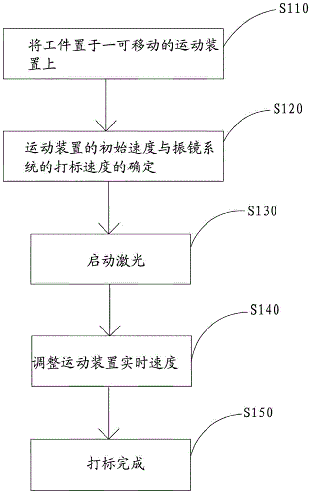
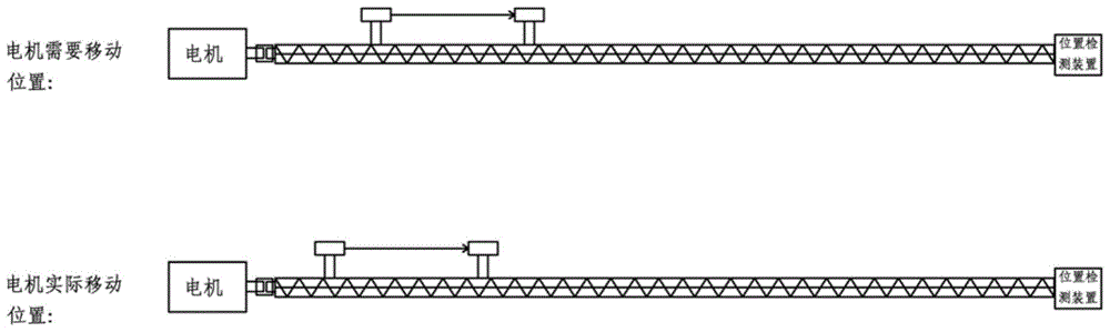
[0024] Such as figure 1 , the embodiment of the present invention provides a laser marking method that extends the marking range. The laser marks the moving workpiece through the galvanometer system. While marking, the position detection device detects the position of the workpiece in real time and detects The information is fed back to the control system, and the control system calculates the actual displacement of the workpiece, and compares the length of the completed marking content on the workpiece combined with the actual displacement of the motion device with the length of the marking range ...


PUM


Abstract

The invention applicable to the field of laser marks and provides a laser marking method for expanding a marking range. While laser is used for marking a movable workpiece by a vibration mirror system, a position detection device is used for detecting the position of the workpiece and feeding back the detection information to a control system; the control system is used for calculating actual displacement of the workpiece and comparing the corresponding length of marked content and the actual displacement with the marking range of a vibration mirror in a workpiece movement direction; a movable speed of the workpiece is controlled according to a compared result, so that a position to be marked of the workpiece is enabled to be always in the marking range of the position detection device. The method is simple to operate. The embodiment of the invention further provides a laser marking system for expanding the marking range.

Description

technical field [0001] The invention belongs to the field of laser marking, in particular to a laser marking method and system for extending the marking range. Background technique [0002] Marking with X, Y vibrating mirror motor scanning has become the most popular and commonly used laser marking method because of its high response, high speed, high precision, stable control and maturity. The biggest defect of this marking method is that the marking range should not be too large, and the higher the precision, the smaller the marking range is required. Currently, the commonly used marking ranges are 40mmX40mm, 80mmX80mm, and 160mmX160mm. The marking range is also relatively large, such as 400mmX400mm, but the marking range is too large, the requirements for the laser focal depth are high, the marking accuracy will be small, and the height from the lens to the marking position is very large in terms of design and operation. etc. problems exist. At present, the application ...

Claims


Application Information

Patent Timeline
Patent Type & Authority Patents(China)
IPC IPC(8): B41J2/435B41J29/393
Inventor 黄柏元陈璋曹洪涛吕启涛高云峰
Owner HANS LASER TECH IND GRP CO LTD
Why Eureka
Try Eureka