
A battery automatic marking machine

An automatic, battery-powered technology, applied in typewriters, printing devices, printing, etc., can solve the problems of easy danger, small activity space, small printing range, etc., and achieve lower labor intensity, wider marking range, and larger marking range Effect

Active Publication Date: 2019-11-12
ANHUI WANLI FOODS CO LTD
View PDF16 Cites 0 Cited by
  • Summary
  • Abstract
  • Description
  • Claims
  • Application Information

AI Technical Summary

Problems solved by technology

[0002] A battery refers to a cup, tank, or other container or a part of a composite container filled with an electrolytic solution and a metal electrode to generate current, a device that can convert chemical energy into electrical energy; the battery is easy to charge and discharge, and is not affected by the external climate and temperature. Influenced by the influence, the performance is stable and reliable, and it plays a great role in all aspects of modern social life. In the process of battery processing, the battery needs to be packaged and marked. Because the traditional manual labeling consumes a lot of labor, the efficiency is low, and the labeling The label storage time is short, therefore, the demand for battery automatic marking machines is increasing
[0003] At present, among the marking equipment in the market, the pneumatic marking machine is easy to operate and has high efficiency. However, the force of the printing needle may be uneven, sometimes the force is strong, and sometimes the force is small. Dangerous, the pneumatic marking machine on the market lacks protective devices, which is easy to cause danger, and the marking machine is difficult to adjust the height, the activity space is small, and the printing range is small, which greatly reduces the scope of application. Therefore, a battery automatic marking machine is proposed to solve the above problems. Standard machine

Method used


Image

  • A battery automatic marking machine
  • A battery automatic marking machine
  • A battery automatic marking machine

Examples


Embodiment Construction

[0020] The following will clearly and completely describe the technical solutions in the embodiments of the present invention with reference to the accompanying drawings in the embodiments of the present invention. Obviously, the described embodiments are only some, not all, embodiments of the present invention. Based on the embodiments of the present invention, all other embodiments obtained by persons of ordinary skill in the art without making creative efforts belong to the protection scope of the present invention.

[0021] see Figure 1-3 , the present invention provides a technical solution:

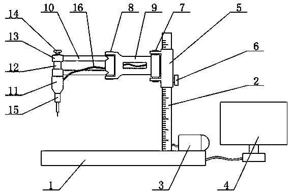
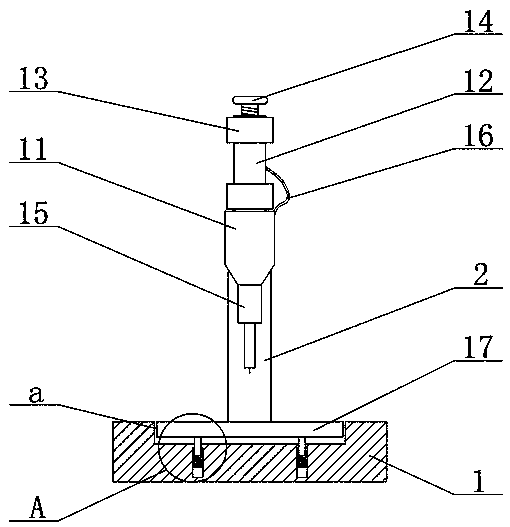
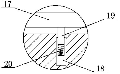
[0022] An automatic battery marking machine, comprising a base 1 and a first connecting beam 9, the right side of the base 1 is provided with a display controller 4, the top of the base 1 is fixedly connected with a column 2, and the right side of the column 2 is provided with Compress the air pump 3, the scale is marked on the column 2, the column 2 is covered with a lifting cyli...


PUM


Abstract

The invention relates to the technical field of automatic marking, in particular to an automatic marking machine for batteries. The automatic marking machine comprises a base and a first connection beam. A display screen controller is arranged on the right side of the base, a stand column is fixedly connected to the top end of the base and sleeved with a lifting barrel, the lifting barrel is in sliding connection with the stand column, a first rotating shaft is rotationally connected to the left end of the lifting barrel, the first rotating shaft is fixedly connected to the right end of a first connection beam, a second connection beam is arranged at the left end of the first connection beam, a vertically-arranged fixing ring is connected to the left end of the second connection beam, a printing head is arranged below the fixing ring, an air pipe is connected to the printing head, a fixing rod is fixedly connected to the inner side of the fixing ring, a printing needle pipe is arrangedin the fixing rod, a screw rod is fixedly connected to the top end of the printing needle pipe, and a horizontal plate is arranged under the printing needle pipe. The automatic marking machine for the batteries can carry out pneumatic marking on the batteries, is high in working efficiency and good in marking effect, is provided with a battery protection device and is worthy of popularization.

Description

technical field [0001] The invention relates to the technical field of automatic marking, in particular to a battery automatic marking machine. Background technique [0002] A battery refers to a cup, tank, or other container or a part of a composite container filled with an electrolytic solution and a metal electrode to generate current, a device that can convert chemical energy into electrical energy; the battery is easy to charge and discharge, and is not affected by the external climate and temperature. Influenced by the influence, the performance is stable and reliable, and it plays a great role in all aspects of modern social life. In the process of battery processing, the battery needs to be packaged and marked. Because the traditional manual labeling consumes a lot of labor, the efficiency is low, and the labeling The label storage time is short, therefore, the demand for automatic battery marking machines is increasing. [0003] At present, among the marking equipm...

Claims


Application Information

Patent Timeline
Patent Type & Authority Patents(China)
IPC IPC(8): B41J3/407B41J29/393
CPCB41J3/4073B41J29/393
Inventor 孟书芳
Owner ANHUI WANLI FOODS CO LTD
Learn More