
Detection jig

A technology for detecting fixtures and testing signals, applied in static indicators, instruments, etc., can solve problems such as panel damage, probe damage, affecting product design and production, and achieve the effect of comprehensive and accurate judgment.

Active Publication Date: 2015-05-20
HEFEI BOE OPTOELECTRONICS TECH +1
View PDF6 Cites 15 Cited by
  • Summary
  • Abstract
  • Description
  • Claims
  • Application Information

AI Technical Summary

Problems solved by technology

[0003] However, in the process of lighting detection for high-PPI panels, due to the fact that the product pixels are getting smaller and thinner, the alignment accuracy is required to be within 2 μm, and the defect detection also requires a larger inspection angle of up, down, left, and right. For special defects such as color moiré (Mura), it must be found in the case of defective product comparison inspection, and the detection equipment used before is very easy to cause damage to the panel and probe caused by the operation, which greatly restricts the high-quality The yield rate of PPI products affects the design and production of subsequent products

Method used


Image

  • Detection jig
  • Detection jig
  • Detection jig

Examples


Embodiment Construction

[0043] Specific embodiments of the present invention will be described in detail below in conjunction with the accompanying drawings. It should be understood that the specific embodiments described here are only used to illustrate and explain the present invention, and are not intended to limit the present invention.

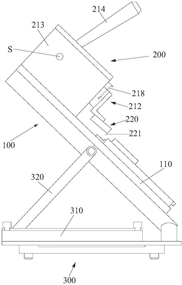
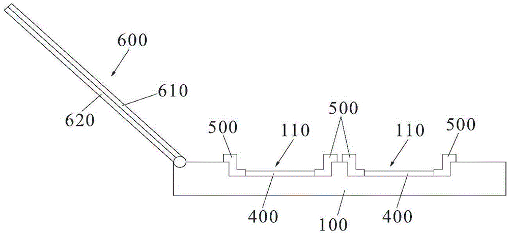
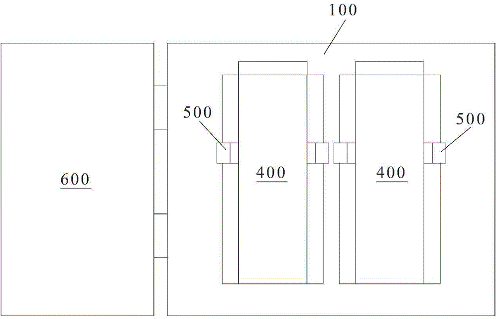
[0044] Such as Figure 1 to Figure 4 As shown in , the present invention provides a testing fixture, which includes a carrier platform 100 and a test signal output device 200, wherein the testing tool also includes a position adjustment device for adjusting the inclination angle of the carrier platform 100 Mechanism 300, the carrying platform 100 includes a plurality of carrying parts 110, each carrying part 110 is used to carry the display panel 400 to be tested placed on the carrying part 110, and the test signal output device 200 is used to respectively set on multiple A plurality of display panels 400 on the carrying part 110 provide test signals.

[0045]...


PUM


Abstract

The invention provides a detection jig, which comprises a carrying table and a testing signal output device. The detection jig is characterized by also comprising a position adjusting mechanism, wherein the position adjusting mechanism is used for adjusting an inclining angle of the carrying table, the carrying table comprises a plurality of carrying parts, each carrying part is used for carrying a to-be-detected display panel which is arranged on the corresponding carrying part, and the testing signal output device is used for respectively providing testing signals for a plurality of display panels which are arranged on the corresponding carrying parts. The detection jig is suitable for detecting the high-PPI (pixel per inch) display panels.

Description

technical field [0001] The present invention relates to the field of manufacturing display devices, in particular to a testing jig for testing display panels. Background technique [0002] In the flat panel display manufacturing process, in order to quickly and accurately check the product's adverse reaction to the production situation, a panel inspection station is set up in the production line. The general panel inspection engineering inspection is placed after the cutting process, and the probe unit in the special inspection equipment is used to perform probe testing on the panel. Probe test includes open test and color test for panel data lines and gate lines, targeting a single pixel. Use the probe unit to input display signals to the terminal area to detect defects. [0003] However, in the process of lighting detection for high-PPI panels, due to the fact that the product pixels are getting smaller and thinner, the alignment accuracy is required to be within 2 μm, a...

Claims


Application Information

Patent Timeline
Patent Type & Authority Applications(China)
IPC IPC(8): G09G3/00
Inventor 王忠山李明佘梦龙
Owner HEFEI BOE OPTOELECTRONICS TECH
Learn More