Novel anti-drop-beam device

A new type of anti-falling beam technology, applied in bridges, bridge parts, bridge construction and other directions, can solve the problems of unsatisfactory position limit effect and poor anti-vibration effect, and achieve reliable anti-falling beams, good buffering, and improving bearing capacity.

Inactive Publication Date: 2015-05-27
YANGZHOU HANJIANG ZHONGKE NANGONG STRUCTURE MONITORING & CONTROL RES CENT
View PDF7 Cites 12 Cited by
  • Summary
  • Abstract
  • Description
  • Claims
  • Application Information

AI Technical Summary

Problems solved by technology

At present, the commonly used anti-fall beam types are mainly anchor bolt type, block type, steel b

Method used


Image

  • Novel anti-drop-beam device
  • Novel anti-drop-beam device
  • Novel anti-drop-beam device

Examples


Embodiment 1

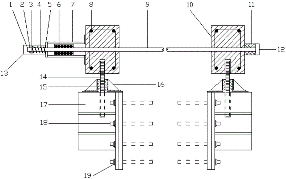
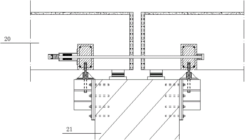
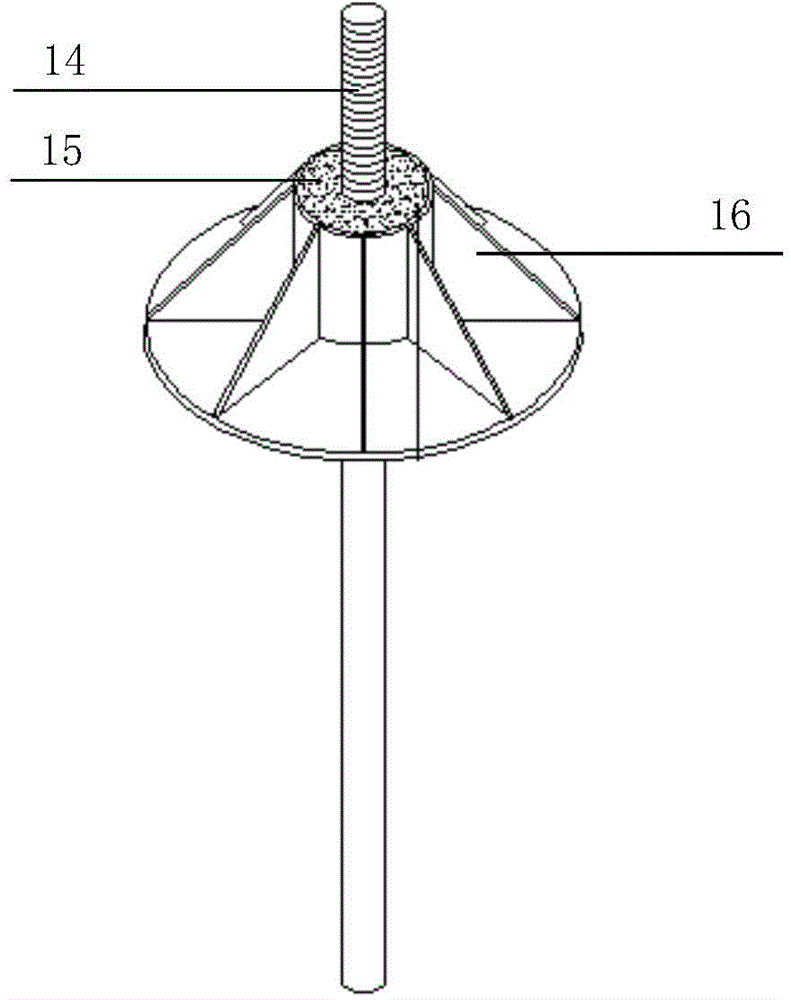
[0029] Such as Figure 1-7 A new anti-drop beam device shown includes two sections of beams 20, one end of the two sections of beams is respectively placed on the pier body 21, including a cable anti-fall beam structure and a limit anti-fall beam structure; In the anti-fall beam structure, two fixed anchor plates 10 are respectively fixed on the two sections of the beam body 20 by rivets 8, and the two fixed anchor plates are connected by a cable 9, and one end of the cable is connected to the fixed anchor plate by a high damping rubber pad 11. On the anchor plate, the rubber pad is provided with a rear cover 12, and the other end of the cable passes through another fixed anchor plate and is connected to the frictional energy dissipation device 6. A sealing cylinder 7 is arranged on the periphery of the frictional energy dissipation device 6, and one side of the sealing cylinder is connected to the frictional energy dissipation device 6. The fixed anchor plate is fixed, and a ...

Embodiment 2

[0033] Such as Figure 1-7 A new anti-drop beam device shown includes two sections of beams 20, one end of the two sections of beams is respectively placed on the pier body 21, including a cable anti-fall beam structure and a limit anti-fall beam structure; In the anti-fall beam structure, two fixed anchor plates 10 are respectively fixed on the two sections of the beam body 20 by rivets 8, and the two fixed anchor plates are connected by a cable 9, and one end of the cable is connected to the fixed anchor plate by a high damping rubber pad 11. On the anchor plate, the rubber pad is provided with a rear cover 12, and the other end of the cable passes through another fixed anchor plate and is connected to the frictional energy dissipation device 6. A sealing cylinder 7 is arranged on the periphery of the frictional energy dissipation device 6, and one side of the sealing cylinder is connected to the frictional energy dissipation device 6. The fixed anchor plate is fixed, and a ...

Embodiment 3

[0038] Such as Figure 1-7 A new anti-drop beam device shown includes two sections of beams 20, one end of the two sections of beams is respectively placed on the pier body 21, including a cable anti-fall beam structure and a limit anti-fall beam structure; In the anti-fall beam structure, two fixed anchor plates 10 are respectively fixed on the two sections of the beam body 20 by rivets 8, and the two fixed anchor plates are connected by a cable 9, and one end of the cable is connected to the fixed anchor plate by a high damping rubber pad 11. On the anchor plate, the rubber pad is provided with a rear cover 12, and the other end of the cable passes through another fixed anchor plate and is connected to the frictional energy dissipation device 6. A sealing cylinder 7 is arranged on the periphery of the frictional energy dissipation device 6, and one side of the sealing cylinder Fixed with the fixed anchor plate, the other end is provided with a buffer 5, the cable passes thro...


PUM


Abstract

The invention discloses a novel anti-drop-beam device, and belongs to the technical field of an anti-drop-beam of a bridge. The device comprises an inhaul cable anti-drop-beam structure and a limit anti-drop-beam structure; in the inhaul cable anti-drop-beam structure, two fixed anchored plates are respectively fixed on two beam bodies, the two fixed anchored plates are connected through an inhaul cable, one end of the inhaul cable is connected on one fixed anchored plate through a rubber cushion, and the other end of the inhaul cable passes through another fixed anchored plate and then is connected with a friction energy consumption device and the lower ends of the two fixed anchored plates are fixedly connected with the limit anti-drop-beam structure; in the limit anti-drop-beam structure, the upper ends of two vertical anchor rods are respectively fixed at the lower ends of the two fixed anchored plates, and the lower ends of the two vertical anchor rods are respectively and fixedly connected with the two fixed anchored plates. According to the device provided by the invention, by adopting a way that the inhaul cable anti-drop-beam structure and the limit anti-drop-beam structure are combined, the stability of the bridge can be improved, the effects of buffering as well as damping and energy dissipation can be realized, and the secondary defense anti-drop-beam effect can be reached.

Description

technical field [0001] The invention belongs to the technical field of bridge anti-drop beams, in particular to an anti-fall beam device. Background technique [0002] With the development of the economy, the country has also increased its efforts in infrastructure construction, and bridges and construction projects have developed at a high speed. China is moving from a "bridge country" to a "bridge power country". In the work of earthquake prevention and disaster reduction, the lifeline project is the most important link, and the bridge is one of the lifeline projects. As a transportation hub, it is the most important thing, and it is closely related to people's life. [0003] The destruction of the earthquake will bring difficulties to post-disaster rescue work, even cause traffic paralysis, trigger secondary disasters, and bring huge losses of life and property to the country and people. Therefore, after the 5.12 Wenchuan Earthquake, a special mission was put forward for...

Claims


Application Information

Patent Timeline
IPC IPC(8): E01D19/00
CPCE01D19/00
Inventor 孙广俊李鸿晶张鹤年刘同康罗韧岳锌牛强赵纪军
Owner YANGZHOU HANJIANG ZHONGKE NANGONG STRUCTURE MONITORING & CONTROL RES CENT
Why Eureka
Try Eureka