
Double-cantilever steel damping device

A technology of steel damping and double cantilever, which is applied to bridge parts, bridges, buildings, etc., can solve the problems that the horizontal energy consumption limit function is difficult to be guaranteed, the mechanical behavior can no longer be guaranteed, and the universality of space installation is limited. , to achieve the effects of strong controllability of mechanical behavior, widening application potential, and low vertical space requirements

Pending Publication Date: 2021-02-19
TONGJI UNIV +1
View PDF2 Cites 1 Cited by
  • Summary
  • Abstract
  • Description
  • Claims
  • Application Information

AI Technical Summary

Problems solved by technology

At the same time, the application of existing cases shows that after several years of service, the mechanical behavior of the steel damping device during earthquakes can no longer be guaranteed due to the settlement of the pier column, and its performance during earthquakes is worthy of further discussion
[0003] Chinese patents CN101748685A and CN102953327A have successively disclosed a slidable cylindrical soft steel damper and a triangular plate transverse damping damper suitable for bridge structures, both of which meet the longitudinal sliding of the bridge through the structure of the ball head and the chute displacement requirements, it is not yet possible to provide the function of tensile strength in the vertical direction
At the same time, because the energy dissipation behavior of the steel damping element is very sensitive to the vertical position of the ball head, it is difficult to guarantee the horizontal energy dissipation limit function under the settlement of the bridge pier or vertical earthquake.
In addition, when the demand for seismic displacement is large, the height of the two damping elements is high, and the connection parts such as the top and bottom plates require a large vertical space, and the universality of space installation is very limited.
At the same time, due to the high height of the damping element body, the bending moment at the root is relatively large. Under the earthquake, the anchoring problem of the root under the action of bending and shearing is a more difficult problem.

Method used


Image

  • Double-cantilever steel damping device
  • Double-cantilever steel damping device
  • Double-cantilever steel damping device

Examples


Embodiment 1

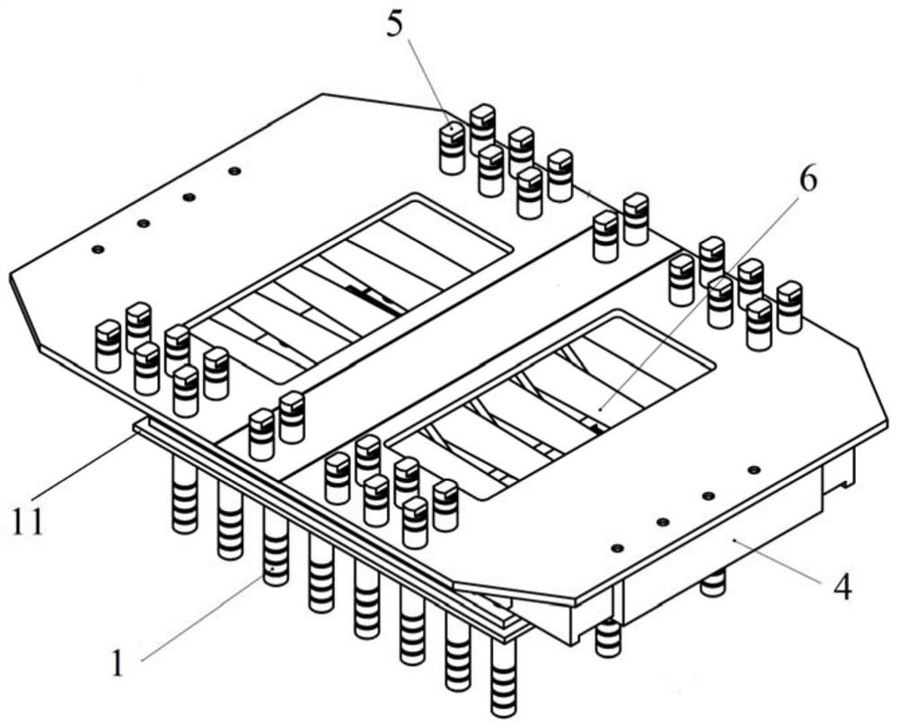
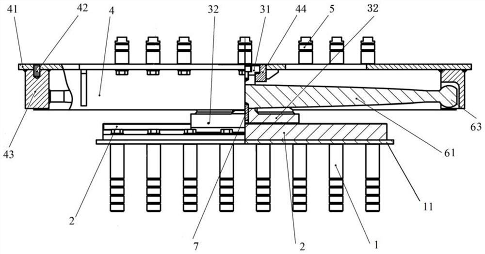
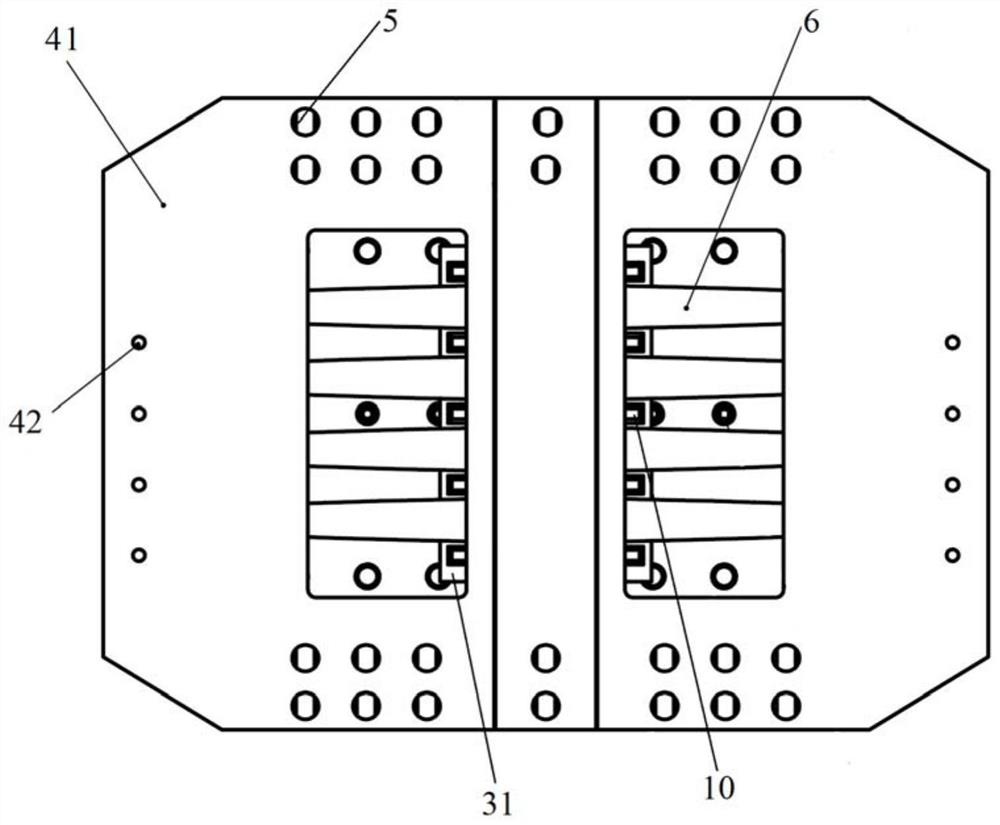
[0068] refer to Figure 1-Figure 9 , the present embodiment provides a double cantilever steel damping device, which is a vertical pull-out resistant double cantilever bar-shaped steel damping device. Including ground anchor bolt 1, base slide plate 2, guide base 3, thrust steel box 4, connecting beam bolt 5 and symmetrical double cantilever steel damping unit 6, the base slide plate 2 is connected above the bottom plate 11, and the ground anchor bolt 1 is connected to Below the bottom plate 11, the ground anchor bolt 1 is used to realize the connection between the base slide plate 2 and the base plate 11 and the top of the pier, the lower part of the guide base 3 is slidingly connected with the upper part of the base slide plate 2, and the guide base 3 and the base slide plate 2 form the second A tensile contact pair; the middle part of the symmetrical double cantilever steel damping unit 6 is connected to the guide base 3, the two ends of the symmetrical double cantilever st...

Embodiment 2

[0081] refer to Figure 10-Figure 13 , the present embodiment provides a double cantilever steel damping device, which is a vertical non-drawing-resistant double cantilever bar-shaped steel damping device.

[0082] The difference from Embodiment 1 is that the second slideway is a non-tensile contact pair, the corresponding second slideway 31 adopts a rectangular convex structure, and the second slider 44 adopts a concave shape that is suitable for the concave-convex structure of the rectangular convex structure. Chute structure.

Embodiment 3

[0084] refer to Figure 14-Figure 18 , the present embodiment provides a double cantilever steel damping device, which is a vertical pull-out resistant double cantilever diamond-shaped steel damping device.

[0085] The difference from Embodiment 1 is that in this embodiment, the symmetrical double-cantilever steel damping unit 6 is a symmetrical double-cantilever diamond-shaped steel damping unit 62, that is, the two cantilever steel bodies form a diamond-shaped steel plate, and the symmetrical double-cantilever diamond-shaped steel damping unit The cantilever end of 62 is a cylindrical structure 64, and the cylindrical structure 64 extends into the double-row thrust holes 46 provided on the thrust steel box 4. The double-row thrust holes 46 are elliptical, and the direction along the bridge is the long axis direction. Determined by the displacement stroke of the symmetrical double-cantilever diamond-shaped steel damping unit 62, along the direction of the transverse bridge i...


PUM


Abstract

The invention relates to a double-cantilever steel damping device. The device comprises a bottom plate, a base sliding plate, a guide base, a symmetrical double-cantilever steel damping mechanism anda thrust steel box, the base sliding plate is fixedly installed on the bottom plate, and the guide base capable of sliding in the longitudinal direction of the base sliding plate is further arranged on the base sliding plate. The thrust steel box is arranged on the guide base in a sliding mode in the transverse direction, the middle of the symmetrical double-cantilever steel damping mechanism is connected with the guide base, and the two ends of the symmetrical double-cantilever steel damping mechanism are movably connected with the two sides of the thrust steel box respectively. The verticalanti-drawing function can be selectively provided, and the requirement of a bridge in a high-intensity area for vertical limiting of the seismic mitigation and absorption device is met.

Description

technical field [0001] The invention belongs to the technical field of damping devices and relates to a double cantilever steel damping device. Background technique [0002] In the seismic isolation design of bridges, seismic isolation bearings are generally used to release the huge inertial force of the main girder, and then the displacement of the main girder is limited within an acceptable range by an energy-dissipating limit device. For long-span bridges, viscous dampers are generally used for vibration control along the bridge direction, and metal dampers are generally used for transverse bridge direction; Application prospect. As a common type of metal dampers, steel damping devices are the most competitive, so various types of steel damping devices have been explored and applied in bridge structures in recent years. In the above cases, it is required to be able to adapt to the expansion and contraction deformation of the bridge girder in the longitudinal direction d...

Claims


Application Information

Patent Timeline
Patent Type & Authority Applications(China)
IPC IPC(8): E01D19/00
CPCE01D19/00
Inventor 王君杰高昊钱云峰杨俊沈育伟张诗悦
Owner TONGJI UNIV
Learn More