A leaf incineration system

A technology for fallen leaves and incinerators, which is applied in the field of leaf incineration, can solve the problems of production efficiency and cost impact, increase processes, and high impurity content, and achieve the effects of reducing material size, improving burning effect, and ensuring burning effect.

Inactive Publication Date: 2017-01-25
ZHEJIANG SCI-TECH UNIV
View PDF8 Cites 0 Cited by
  • Summary
  • Abstract
  • Description
  • Claims
  • Application Information

AI Technical Summary

Problems solved by technology

However, at present, in the process of burning, a large amount of solid particles are likely to be generated, thereby forming smoke and dust, which has an adverse impact on the surrounding environment: because of centralized burning, it is easy to have insufficient burning process, the utilization rate of raw materials is limited and it will lead to impurities The content is too high; and due to incomplete combustion, there are more impurities and residual materials in the product, which requires subsequent treatment, which increases the process and has a negative impact on production efficiency and cost

Method used


Image

  • A leaf incineration system
  • A leaf incineration system
  • A leaf incineration system

Examples


Embodiment 1

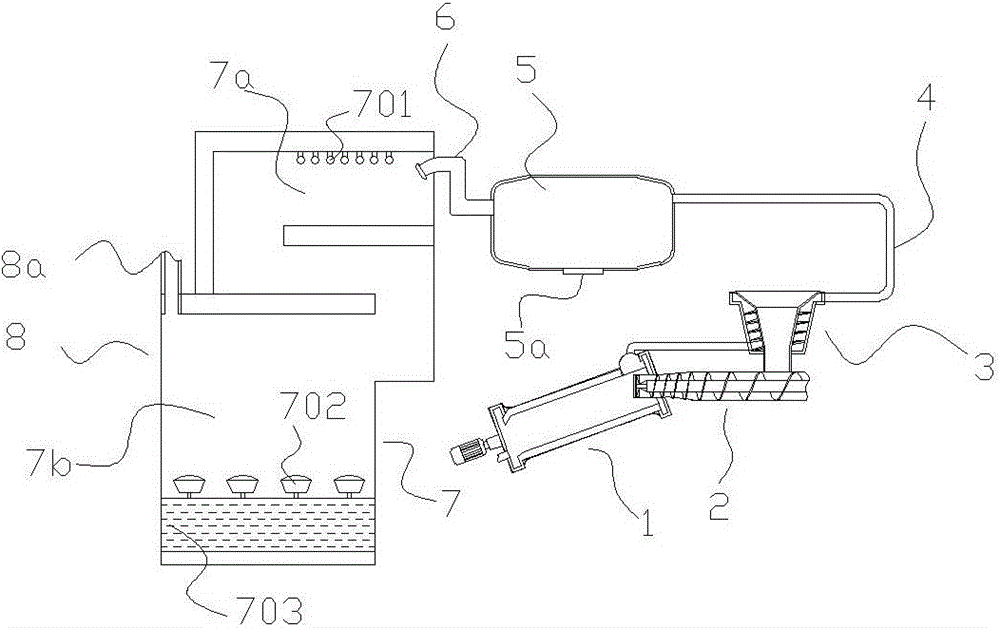
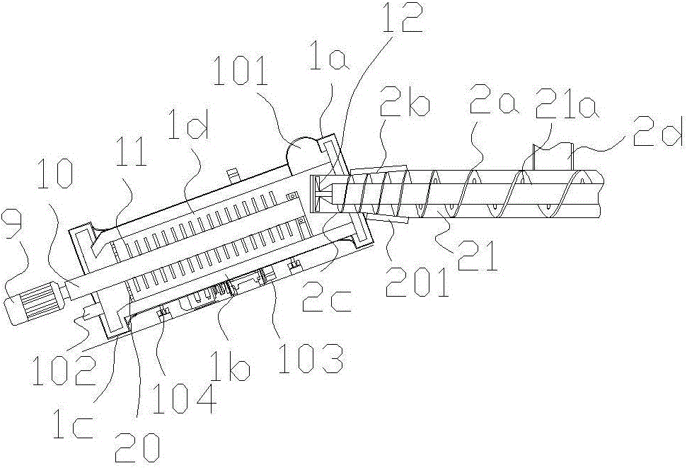
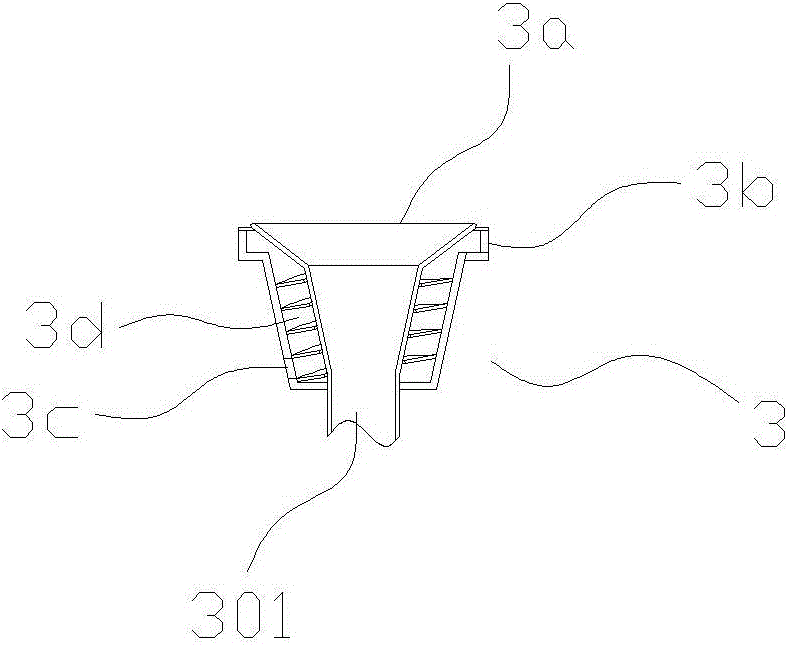
[0023] Such as figure 1 , figure 2 , image 3 In the shown embodiment 1, a kind of fallen leaves incineration system comprises an incinerator 1, a feeding device 2, a smoke cleaning device 7 and a preheating device 3; The furnace is arranged obliquely, and the height of the furnace head is higher than that of the furnace tail. There is an incineration chamber 1d inside the furnace body, combined with figure 2 As shown, the incineration chamber is provided with a transmission main shaft 10 driven by the main motor 9, and a plurality of bulk materials 11 for moving materials are arranged on the transmission main shaft. The bulk materials are in a hollow tubular structure, along the diameter of the transmission main shaft Arranged in the direction, it also includes an air pump that can blow air into the inner cavity of the main shaft, and the central through hole of the bulk body communicates with the inner cavity of the main shaft. The furnace head is provided with a feed ...

Embodiment 2

[0031] The basic structure and implementation mode of this embodiment are the same as embodiment 1, and its difference is, as Figure 4 Shown, also comprise a cleaning motor, the transmission main shaft is provided with the main shaft inner chamber, and a transmission inner shaft 17 coaxial with the transmission main shaft stretches among the main shaft inner chamber. One end of the transmission inner shaft can be driven to rotate by the output shaft of the cleaning motor, and the other end is connected with the bearing of the inner shaft, and multiple cleaning devices are arranged on the transmission main shaft. The dirt removal device comprises a dirt ball 18, a limit ball 19, a ball receiving spring 16, a slide bar 15, a slide hole arranged on the drive shaft wall, the slide bar and the slide hole are slidably matched, and the dirt ball and the limit ball are respectively connected with the The two ends of the slide rod are connected, and the ball receiving spring is set on...


PUM


Abstract

The invention discloses a fallen leaf incineration system. The fallen leaf incineration system comprises an incinerator, a feeding device used for feeding materials into the incinerator, a smoke purifying device used for purifying flue gas exhausted from the incinerator, and a preheating device, wherein the incinerator comprises a furnace body, a furnace head and a furnace tail; a driving main shaft driven by a main motor is arranged in an incineration cavity of the incinerator; a plurality of material dispersing bodies used for shifting the materials are arranged on the driving main shaft; the feeding device comprises a feeding cylinder stretching into the incineration cavity from a feeding inlet; a feeding auger is arranged in the feeding cylinder; the preheating device comprises a preheating hopper and a spiral flue which winds around the preheating hopper; the smoke purifying device comprises a smoke exhausting outer passage and a water falling pond; a plurality of water spraying heads are arranged above the interior of the smoke exhausting outer passage. The invention aims to provide the fallen leaf incineration system, which can effectively incinerate animal carcasses in a concentrating way, is stable and effective in an incineration process, can guarantee full incineration, can effectively treat generated flue gas and can prevent flue dust pollution.

Description

technical field [0001] The invention relates to the field of fallen leaves burning, in particular to a fallen leaves burning system. Background technique [0002] At present, there are often many dead leaves or dry grass, etc. If the dead leaves or dry grass are directly used as fertilizers for landfill, it will take a long time for the decomposition process to be absorbed before they can be converted into soil fertility. There are many land resources, and the actual fertilizer supply capacity is relatively poor. Therefore, it can be selected to be incinerated centrally, so as to be burned into plant ash fertilizer for rational use. Plant ash is rich in mineral elements needed for plant growth, among which potassium is the most abundant, generally containing 6-12% potassium; followed by phosphorus, generally containing 1.5-3%; calcium, magnesium, silicon, sulfur and iron are also contained , manganese, copper, zinc, boron, molybdenum and other micronutrients. However, at ...

Claims


Application Information

Patent Timeline
Patent Type & Authority Patents(China)
IPC IPC(8): F23G7/10
CPCF23G7/10
Inventor 万昌江孙永剑
Owner ZHEJIANG SCI-TECH UNIV
Why Eureka
Try Eureka