
Circuit controlled by light touch switch

A switch control circuit, light touch technology, used in electronic switches, electrical program control, program control in sequence/logic controllers, etc.

Active Publication Date: 2015-05-27
KENNEDE ELECTRIONICS MFG CO LTD
View PDF7 Cites 0 Cited by
  • Summary
  • Abstract
  • Description
  • Claims
  • Application Information

AI Technical Summary

Problems solved by technology

How to apply light touch switches in this field poses a major challenge to the design

Method used


Image

  • Circuit controlled by light touch switch

Examples


Embodiment Construction

[0015] Do further expression below by specific embodiment:

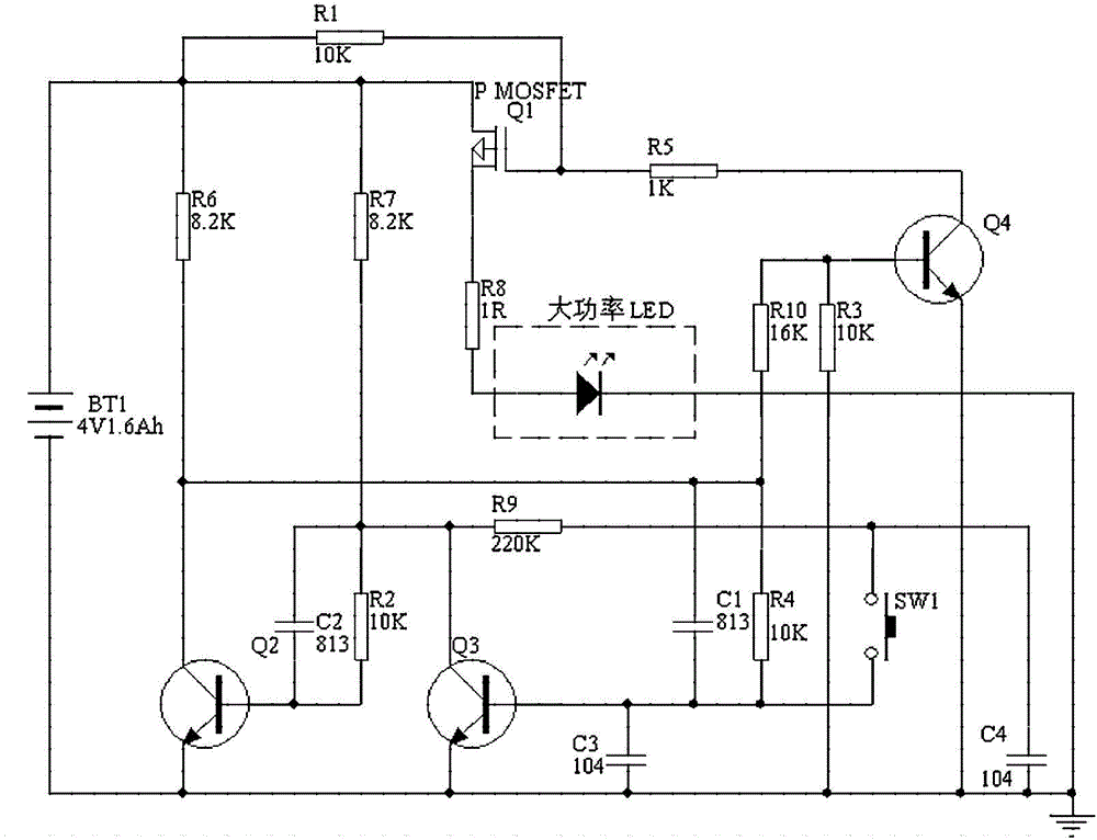
[0016] The drain of the PMOS transistor Q1 is connected to the positive pole of the power supply, the source is connected in series with the resistor R8, the high-power LED is connected to the ground, the gate is connected in series with the resistor R5 to the collector of the NPN transistor Q4, and the resistor R1 is connected between the gate and the drain; NPN The base of the tube Q2 is connected in series with the load circuit connected in parallel by the resistor R2 and the capacitor C2, and connected to the collector of the NPN tube Q3, resistors R7 and R9, the collector series resistor R6 is connected to the positive pole of the power supply, and the emitter is grounded; the NPN tube Q3 The base is connected to capacitors C1, C3, and resistor R4, of which C3 is grounded, and the resistor R9 and tact switch SW1 are connected in series between the collector and the base; the base of NPN tube Q4 is connected to re...


PUM


Abstract

The invention discloses a circuit controlled by a light touch switch. The circuit comprises a PMOS transistor Q1 and NPN transistors (Q2, Q3 and Q4), wherein the drain electrode of the Q1 is connected with a power source; the source electrode of the Q1 is connected with an LED, and earthed; the grid electrode of the Q1 is connected with the collecting electrode of the Q4; a resistor I is connected between the grid electrode of the Q1 and the drain electrode of the Q1; the base electrode of the Q2 is connected with the collecting electrode of the Q3; the collecting electrode of the Q2 is connected with a resistor II and the power source; the emitting electrode of the Q2 is earthed; the base electrode of the Q3 is earthed through a capacitance I; a capacitance II and a switch are connected in series between the collecting electrode of the Q3 and the base electrode of the Q3; the base electrode of the Q4 is connected with a resistor III, earthed, and connected with the base electrode of the Q3; the emitting electrode of the Q4 is earthed. The circuit has the advantages that a small-size light touch switch can be used for controlling a high-current circuit, so that the requirement of portable lighting equipment which is relatively high in power but relatively small in size can be met.

Description

technical field [0001] The invention belongs to the field of switch control circuits, in particular to a light touch switch control circuit. Background technique [0002] With the continuous development of society, people's demand for portable devices is increasing day by day, and there are certain requirements for some key types of products at the same time. Usually, for lighting products with high power, the control switches used are generally closed or cut-off switches, and the volume and withstand current are generally larger than those of tact switches. How to apply light touch switches in this field poses a major challenge to the design. Contents of the invention [0003] Aiming at the above technical problems, the present invention provides a more practical circuit frame, so that the size and current of the lighting product are smaller. [0004] In order to achieve the above object, the present invention is achieved through the following technical solutions: [0...

Claims


Application Information

Patent Timeline
Patent Type & Authority Applications(China)
IPC IPC(8): G05B19/04
CPCH03K17/687H03K17/96
Inventor 田畴胡沃康
Owner KENNEDE ELECTRIONICS MFG CO LTD
Learn More