
Power supply board plug with electric meter

A power plug board and electric meter technology, which is applied in the direction of circuits, electrical components, and measurement of electrical variables, etc., can solve the problems of single function of the power plug board and the inability to measure the power consumption of household appliances, etc., and achieve the effect of accurate power measurement

Inactive Publication Date: 2015-05-27
XIAN DINGZI ELECTRONICS INFORMATION SCI & TECH
View PDF0 Cites 0 Cited by
  • Summary
  • Abstract
  • Description
  • Claims
  • Application Information

AI Technical Summary

Problems solved by technology

[0003] The purpose of the present invention is to overcome the problems in the prior art that the power plug board has a single function and cannot measure the power consumption of household appliances

Method used


Image

  • Power supply board plug with electric meter
  • Power supply board plug with electric meter

Examples


Embodiment 1

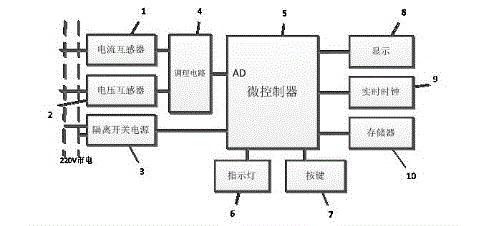
[0011] This embodiment provides a figure 1 A power plug board with an electric meter is shown, including: a current transformer 1, a voltage transformer 2, an isolating switch power supply module 3, a conditioning circuit 4, a microcontroller 5, an indicator light 6, function buttons 7, and a display module 8 , real-time clock 9, storage module 10; Wherein city electric wire passes through the sampling coil of current transformer 1 and voltage transformer 2, current transformer 1, voltage transformer 2 output connect conditioning circuit 4, conditioning circuit 4 output connect microcontroller 5AD interface.

[0012] like figure 1 The indicated indicator lights 6, function keys 7, display module 8, real-time clock 9, and storage module 10 are respectively connected to the microcontroller 5 to form functional modules.

[0013] The switch state of the indicator light 6 indicates whether there is load access at present, and the indicator light is turned on when there is power c...

Embodiment 2

[0016] like figure 1 The isolated switching power supply module 3 shown is connected to the mains network, takes power from the mains network, and connects the output to the microcontroller.

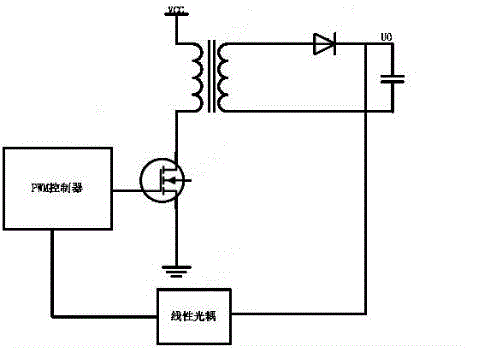
[0017] like figure 2 The isolated switching power supply module 3 shown adopts the technology of isolated high-frequency switching power supply. It not only abandons the huge power frequency transformer in the traditional power supply, but also adopts a high-frequency transformer with small size and high efficiency, and introduces isolated feedback to make the subsequent system and the mains The network is completely isolated, which not only reduces the power consumption of the system, but also increases the security of the system.


PUM


Abstract

The invention belongs to the technical field of household appliances, and relates to a power supply board plug with an electric meter. The power supply board plug specifically comprises a current transformer, a voltage transformer, a disconnector power supply module, a conditioning circuit, a microcontroller, an indicator light, a functional button, a display module, a real time clock, and a memory module. A mains wire passes through sampling coils of the current transformer and the voltage transformer. Outputs of the current transformer and the voltage transformer are connected with the conditioning circuit. The output of the conditioning circuit is connected with the AD interface of the microcontroller. The disconnector power supply module is connected with a mains network so as to take electricity from the mains network. The output of the disconnector power supply module is connected with the microcontroller, so as to provide power for the system. The indicator light, the functional button, the display module, the real time clock and the memory module are respectively connected with the microcontroller so as to form a functional module. The power supply board plug overcomes the defect that a conventional board plug cannot measure electric quantity, is simple and practical, and adopts an electronic measurement way, thereby measuring the electric quantity accurately, providing a reference for household electricity, and allowing people to know the power consumption of various household appliances.

Description

technical field [0001] The invention belongs to the field of household electrical appliances, and in particular relates to a power plug board with an electric meter. Background technique [0002] Power strips are widely used and popularized in daily life and industrial production activities, and become an indispensable part. Where there are electrical appliances, power strips are needed. It becomes a bridge between the mains network and household appliances. It plays a very important role. The traditional power strip only plays the role of expansion and simple power-on or not. With the development of society, the demand for power strips in family life and industrial production activities is increasing, not only in terms of reliability, safety, etc. There are higher and higher requirements in terms of power supply, and at the same time, there are requirements for versatility, which cannot be provided by traditional power sockets. For example, we often want to know the power ...

Claims


Application Information

Patent Timeline
IPC IPC(8): H01R13/66G01R22/06
Inventor 杨福荣
Owner XIAN DINGZI ELECTRONICS INFORMATION SCI & TECH
Learn More