Fault diagnosis method and device
A fault diagnosis and fault technology, applied in the field of communication, to achieve the effect of improving communication overhead and diagnosis reliability
- Summary
- Abstract
- Description
- Claims
- Application Information
AI Technical Summary
Problems solved by technology
Method used
Image
Examples
Embodiment 1
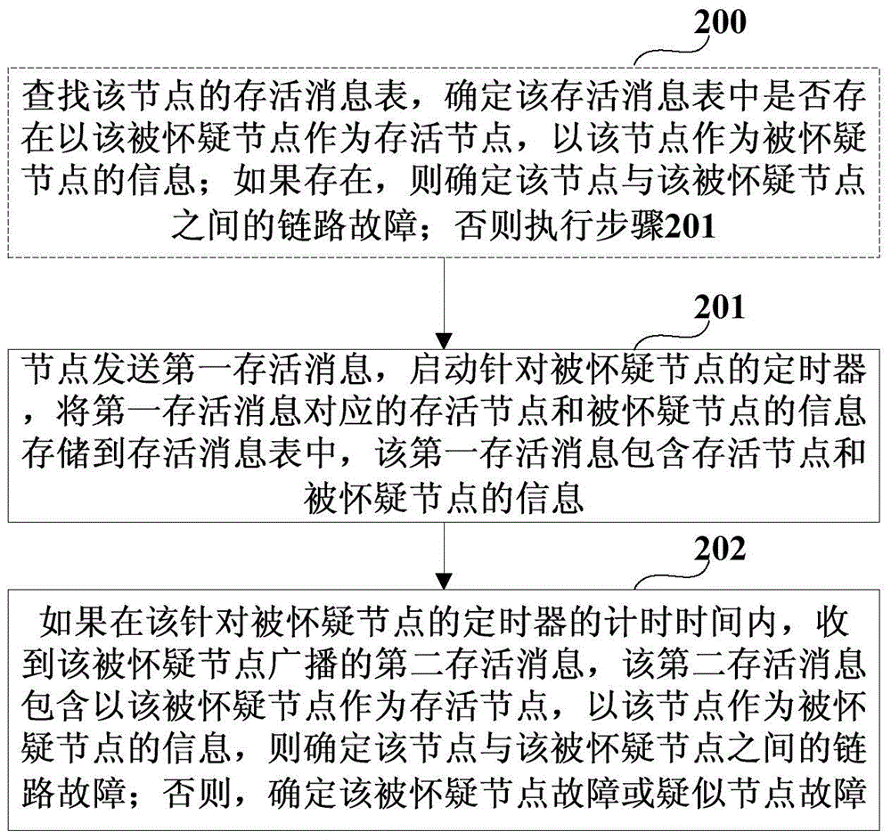
[0031] The embodiment of the present invention provides a fault diagnosis method, which is applied to nodes in an Ad hoc network. figure 2 Is the flow chart of the method, please refer to figure 2 , The method includes:
[0032] Step 201: The node sends a first survival message, starts a timer for the suspected node, and stores the survival node corresponding to the first survival message and the information of the suspected node in the survival message table. The first survival message Contains information about the surviving node and the suspected node, the surviving node is the node;
[0033] Step 202: If within the time period of the timer for the suspected node, a second survival message broadcast by the suspected node is received, the second survival message includes the suspected node as the surviving node and the node as the surviving node Information of the suspected node, it is determined that the link between the node and the suspected node is faulty; otherwise, it is ...
Embodiment 2
[0051] The embodiment of the present invention also provides a fault diagnosis method, which is applied to nodes in the Ad hoc network. Figure 4 Is the flow chart of the method, please refer to Figure 4 , The method includes:
[0052] Step 401: When receiving a survival message (referred to as the third survival message in this embodiment) sent by other nodes, determine the local (ie, the surviving node and the suspected node) according to the information contained in the surviving message Whether the node) is the destination node of the survival message;
[0053] Step 402: If the node is not the destination node of the received survival message, the node forwards the received survival message according to the information contained in the received survival message;
[0054] Step 403: If the node is the destination node of the received survival message, the node performs fault diagnosis and / or processing according to the information contained in the received survival message.
[0055...
Embodiment 3
[0112] The embodiment of the present invention provides a node in an Ad hoc network. Figure 8 Is a schematic diagram of the composition of the node, please refer to Figure 8 , The node 800 includes: a sending unit 801, a storage unit 802, and a first determining unit 803, where:
[0113] The sending unit 801, which sends a first survival message to start a timer for the suspected node, the first survival message contains information about the surviving node and the suspected node, and the surviving node is the node;
[0114] The storage unit 802, which stores the information of the surviving node corresponding to the first surviving message and the suspected node in the surviving message table after the sending unit 801 sends the first survival message
[0115] The first determining unit 803, when receiving the second survival message broadcasted by the suspected node within the timing time of the timer for the suspected node, if the second survival message contains the suspected no...
PUM
 Abstract
Description
Claims
Application Information
 - R&D
- Intellectual Property
- Life Sciences
- Materials
- Tech Scout
- Unparalleled Data Quality
- Higher Quality Content
- 60% Fewer Hallucinations
Browse by: Latest US Patents, China's latest patents, Technical Efficacy Thesaurus, Application Domain, Technology Topic, Popular Technical Reports.
© 2025 PatSnap. All rights reserved.Legal|Privacy policy|Modern Slavery Act Transparency Statement|Sitemap|About US| Contact US: help@patsnap.com


