
A method and device for standardized image acquisition of non-uniform moving objects

A moving object and image acquisition technology, which is applied in the field of image scanning, can solve problems such as different force surfaces of ground induction coils, missed scans, and image errors, and achieve the effects of avoiding phenomena, avoiding missed scans, and increasing viewing width

Inactive Publication Date: 2017-07-07
洛阳灵翔计算机科技发展有限公司
View PDF8 Cites 0 Cited by
  • Summary
  • Abstract
  • Description
  • Claims
  • Application Information

AI Technical Summary

Problems solved by technology

However, the sports car cannot guarantee that it is always moving at a constant speed between the two coil sensors, and the dynamically adjusted shooting frequency can only be realized when the next ground sensing coil is triggered, so there will be errors in the captured images
With a single-line array camera, only one line of images can be taken at a time. During the shooting process, since the speed cannot be kept constant, there may be missing scans, which is not conducive to post-processing
At the same time, it is triggered by the pressure exerted by the sports car, which limits the scope of application and can only be applied to objects with wheels and can directly act on the ground induction coil
And because the ground induction coils are buried underground, it is impossible to guarantee the same depth of burial and the same density of coverings above the ground induction coils, resulting in different force-bearing surfaces of each ground induction coil.
Therefore, even if the ground induction coils are equally spaced, there is no guarantee that each time the ground induction coils are triggered at equal intervals.

Method used


Image

  • A method and device for standardized image acquisition of non-uniform moving objects

Examples


Embodiment approach

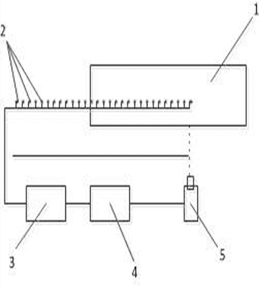
[0013] As an embodiment of the present invention, see figure 1 , including a three-line array CCD camera 5 for collecting image information of moving objects, a computer 4 for receiving and displaying image information of moving objects, three-line array CCD camera 5 and computer 4 two-way communication, and using three-line array CCD camera 5 The shooting position is a section area where the starting position is provided with a plurality of laser sensors 2 arranged at equal intervals, the spacing between the laser sensors 2 is equal to the imaging range of the three-line array CCD camera 5, and the plurality of laser sensors 2 are connected To the signal acquisition card 3 , the signal acquisition card 3 processes the received signal of the laser sensor 2 , and transmits the processed signal data to the computer 4 .

[0014] The method of the device for standardized image acquisition of non-uniform moving objects is as follows: In an area extending a certain distance to one s...


PUM


Abstract

The invention discloses a method and a device for acquiring standard images of non-uniform velocity moving objects. In a region in which the photographing position, as a start position, of a three-line array CCD camera extends toward one side by a distance, laser sensors which are arranged at equal intervals are used for dividing the region into a plurality of equal intervals; the distance between the three-line array CCD camera and the surface of an object passing through the region is adjusted according to the intervals of the laser sensors and the focal length of the three-line array CCD camera, so that the imaging range of the three-line array CCD camera is equal to the intervals among the laser sensors; the three-line array CCD camera is controlled by signals generated by a moving object passing the region by sequentially blocking the laser sensors to intermittently acquire images of the moving object, and image data are transmitted to a computer to form continuous and uninterrupted standard images. The device is easy to operate; the laser sensors are utilized for directly triggering the three-line array camera to photograph without adjusting the photographing frequency of the camera, so that the scanning leakage phenomenon can be prevented effectively.

Description

technical field [0001] The invention relates to the technical field of image scanning, in particular to an image acquisition method and device capable of realizing standardization of non-uniform moving objects. Background technique [0002] The single-line array camera only collects one line of image information at a time. Only when the object is moving at a constant speed can the image captured by the single-line array camera be guaranteed to be error-free. However, the object cannot be guaranteed to move at a constant speed all the time, so it can only rely on external equipment, such as installing an encoder on the rotating shaft of the moving object, to collect the speed in real time and adjust the shooting frequency in real time. However, some devices cannot be properly installed on moving objects, so the shooting frequency cannot be adjusted in real time, resulting in stretched or compressed images. [0003] In the prior art, as in the invention patent CN103439752A an...

Claims


Application Information

Patent Timeline
Patent Type & Authority Patents(China)
IPC IPC(8): H04N7/18H04N5/232
Inventor 梁灵飞普杰信刘中华董永生杨春蕾王晓红
Owner 洛阳灵翔计算机科技发展有限公司
Learn More