Heating apparatus for a MEMS sensor

a technology of mems sensor and heating apparatus, which is applied in the direction of electrical apparatus, microelectromechanical systems, and electromechanical devices, etc., can solve the problems of high current density, high current density, and difficult to meet the needs of the user, so as to achieve uniform width, increase width, and uniform spacing

Active Publication Date: 2017-05-11
ROBERT BOSCH GMBH
View PDF4 Cites 2 Cited by
  • Summary
  • Abstract
  • Description
  • Claims
  • Application Information

AI Technical Summary

Benefits of technology

[0018]A preferred embodiment of the heating apparatus is characterized in that the supply lead element has a definedly decreasing width proceeding over a heating region; and that the return lead element has a definedly increasing width proceeding over the heating region. It is thereby possible to configure the current density to be substantially constant in all the elements recited.
[0019]A further preferred expression of the heating apparatus provides that the supply lead element and the return lead element are each, in the heating region, as wide as a total width of the heating elements disposed in a current flow direction. A general principle of a manufacturing specification for the heating apparatus is thereby furnished, with which the aforesaid effect regarding current density distribution can easily be implemented.
[0020]A further preferred embodiment of the heating apparatus provides that profiles of the widths of the supply lead element and of the return lead element are configured linearly, and the heating elements are configured to be of uniform width and to have a substantially identical spacing from one another. A particularly easily implemented principle for the individual elements of the heating apparatus is thereby furnished, with which simple manufacture of the heating apparatus is promoted.
[0021]A further preferred embodiment of the heating apparatus is notable for the fact that a homogeneous temperature distribution is configurable with the heating elements in the heating region. A sensing characteristic for a sensor can thereby be improved.

Problems solved by technology

Reliability in this context is problematic, especially in conjunction with miniaturization of the sensors for use in mobile user devices such as smartphones.
In this connection, electromigration can represent a particularly relevant damage mechanism that can lead to rapid failure of the aforesaid heating structures as a result of design weaknesses.
Miniaturization of the sensors and correspondingly of the conductor paths generally results in a higher current density and can aggravate the problems even more.
The result, because of the fact that a diaphragm on which the heating apparatus is disposed is a poor thermal conductor, is that the temperature distribution in the heater region is homogenized on the diaphragm.

Method used


Image

  • Heating apparatus for a MEMS sensor
  • Heating apparatus for a MEMS sensor
  • Heating apparatus for a MEMS sensor

Examples


Embodiment Construction

[0038]An aspect of the present invention involves furnishing a specific design for a heating element or heating apparatus for gas sensors or other applications having micro-heating devices, which design is largely resistant to electromigration and thereby promotes a longer service life and greater reliability of the gas sensors.

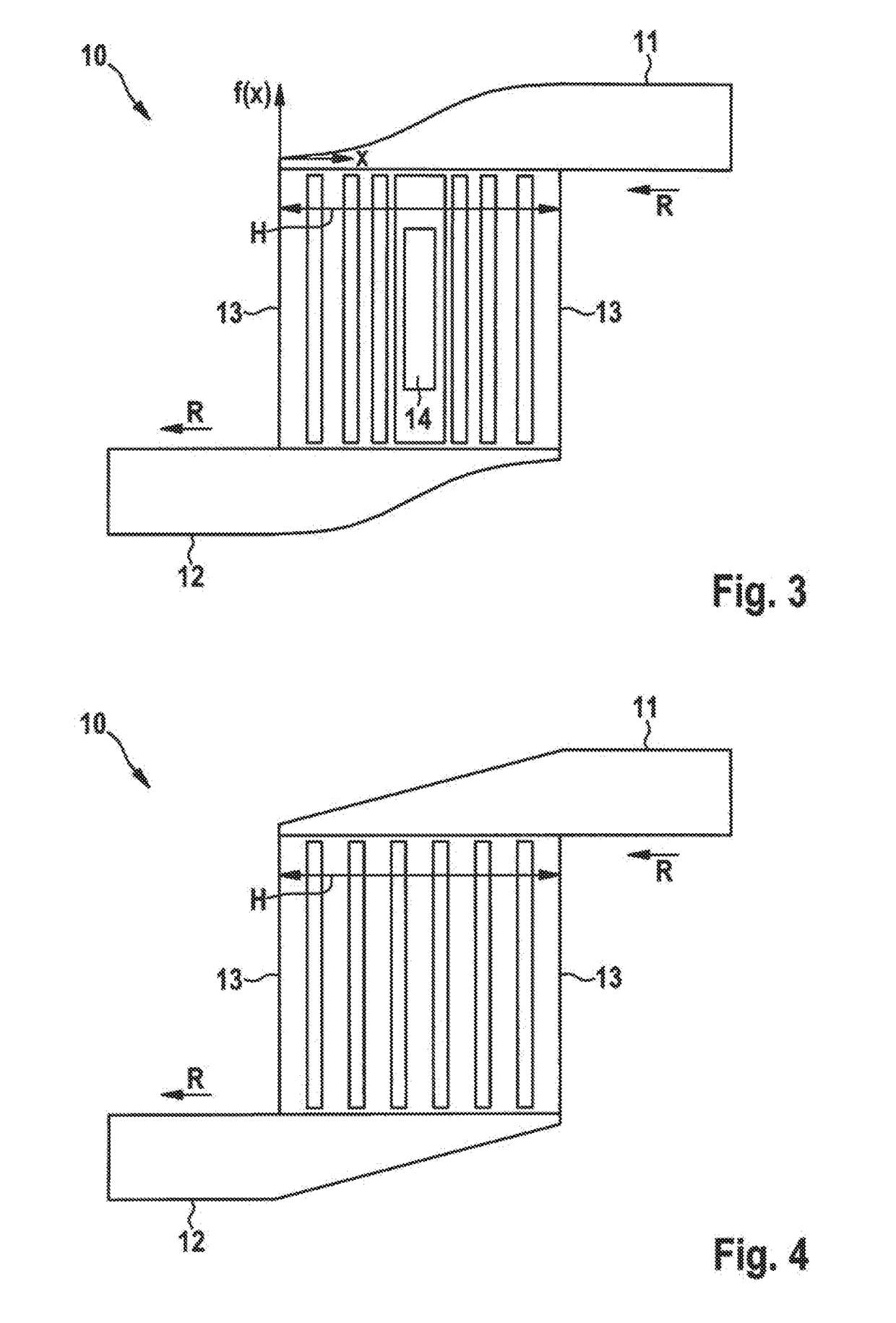
[0039]Provision is made in particular to implement a specific shape of a thin-layer metal heating element for a MEMS gas sensor. The heating element is implemented on a diaphragm, and is responsible for reaching the temperature necessary for the chemical reactions. The proposed heating element can, however, also advantageously be utilized in other, in particular chemical, sensor elements that require an elevated operating temperature and / or permit a similar structure.

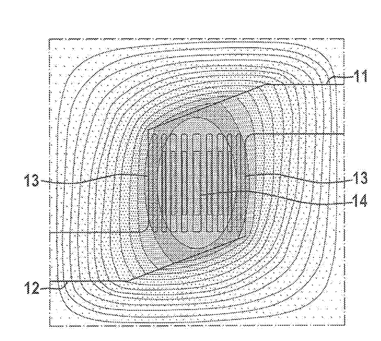
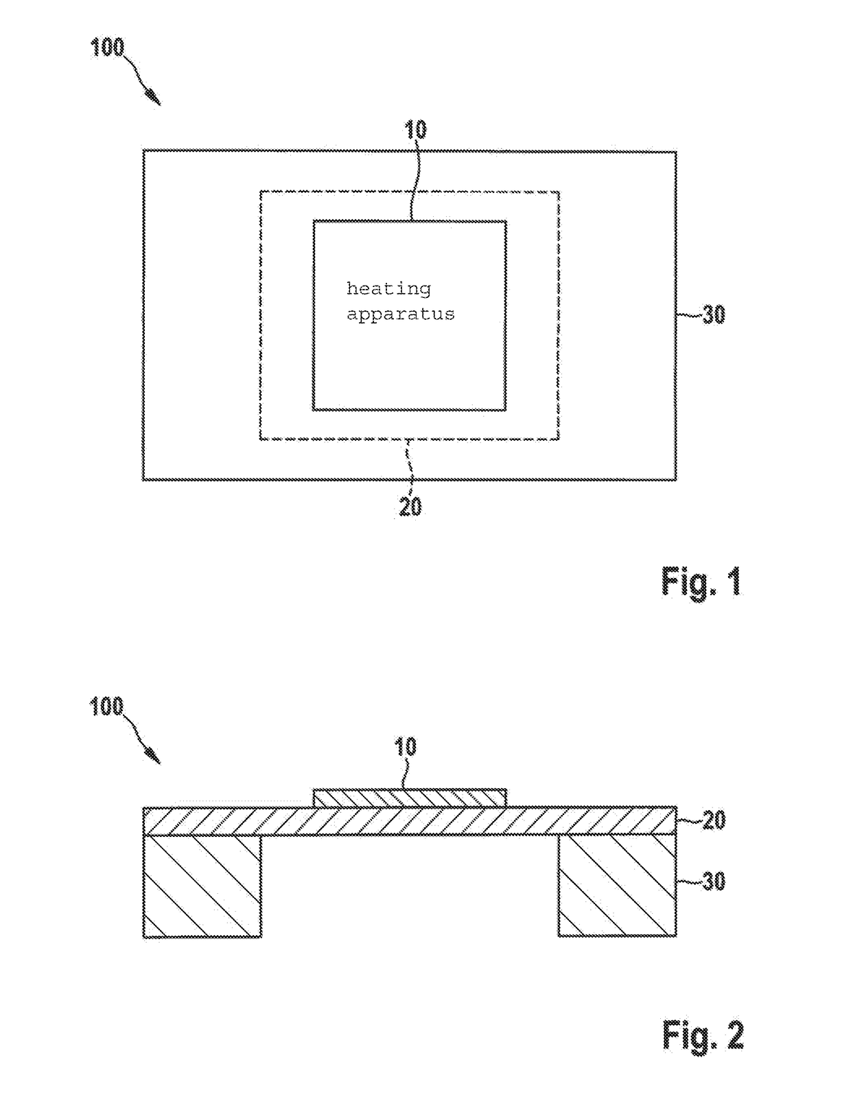
[0040]A generalized MEMS sensor 100 is depicted in FIG. 1 in a schematic plan view. It encompasses a chip or support 30 on which a diaphragm 20 is applied. The chip material is removed from the b...


PUM


Abstract

A heating apparatus for a MEMS sensor, comprising a metallic supply lead element for electric current; a metallic return lead element for electric current; and a defined number of metallic heating elements configured between the supply lead element and the return lead element, a substantially constant electrical current density being configurable in the supply lead element, in the return lead element, and in the heating elements.

Description

CROSS REFERENCE[0001]The present application claims the benefit under 35 U.S.C. §119 of German Patent Application No. DE 102015222072.9 filed on Nov. 10, 2015, which is expressly incorporated herein by reference in its entirety.FIELD[0002]The present invention relates to a heating apparatus for a MEMS sensor. The present invention further relates to a method for manufacturing a heating apparatus for a MEMS sensor.BACKGROUND INFORMATION[0003]Conventional metal-oxide-based gas sensors are used for the detection and quantification of various gases. These sensors typically require temperatures of up to 400° C. in order to function. In a MEMS embodiment, such sensors are often implemented with a silicon dioxide or silicon nitride diaphragm on which a heating element made of platinum or other materials is disposed. Reliability in this context is problematic, especially in conjunction with miniaturization of the sensors for use in mobile user devices such as smartphones.[0004]In this conne...

Claims


Application Information

Patent Timeline
Patent Type & Authority Applications(United States)
IPC IPC(8): B81B3/00H05B3/10
CPCB81B3/0021B81B2201/0214B81B2203/0127H05B3/10B81B7/0096B81C1/0069G01N33/0004H05B3/12H05B3/16B81B7/0087
Inventor RUSANOV, RADOSLAV
Owner ROBERT BOSCH GMBH
Why Eureka
Try Eureka