Two-plate injection molding machine and die assembly structure thereof

An injection molding machine, two-platen technology, applied in the field of mold clamping structure of injection molding machines, can solve the problems of complex oil circuit system, not suitable for small and medium-sized two-platen injection molding machines, increase costs, etc., and achieve the effect of simple precision adjustment

Active Publication Date: 2015-06-03
佛山市顺德区震德塑料机械有限公司
View PDF5 Cites 1 Cited by
  • Summary
  • Abstract
  • Description
  • Claims
  • Application Information

AI Technical Summary

Problems solved by technology

In these two mold adjustment structures, the four tie rods or the lock nuts need to add a separate power device, and the oil circuit system be

Method used


Image

  • Two-plate injection molding machine and die assembly structure thereof
  • Two-plate injection molding machine and die assembly structure thereof
  • Two-plate injection molding machine and die assembly structure thereof

Examples


Example Embodiment

[0025] The preferred embodiments of the present invention will be further elaborated below in conjunction with the accompanying drawings.

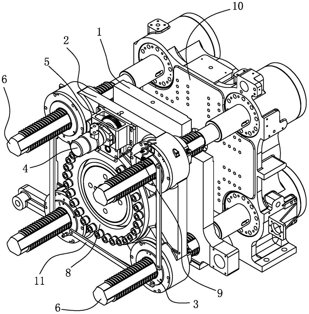
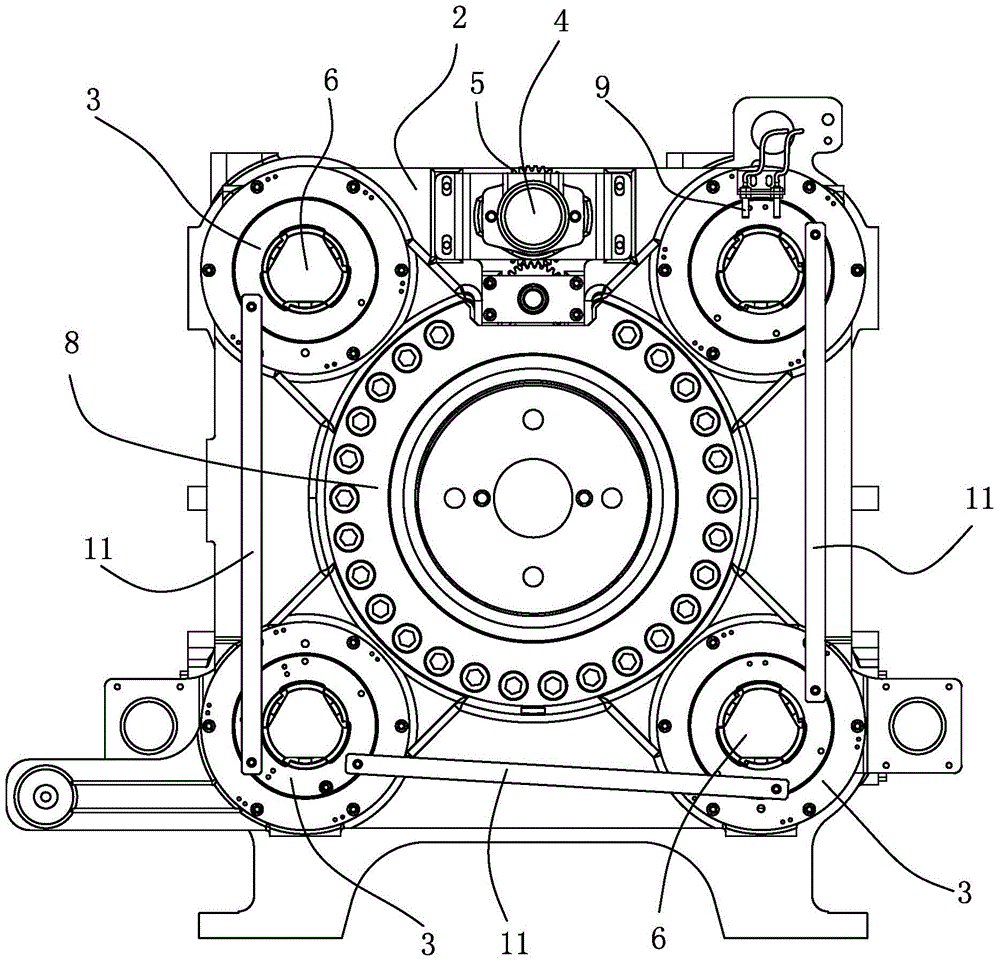
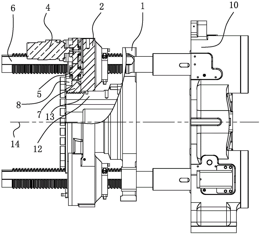
[0026] see Figure 1 to Figure 4 The two-plate injection molding machine and its clamping structure of the present invention include: a certain template 10, a front-moving template 1, a rear-moving template 2, four entry nuts 3, a transmission power device 4, a transmission gear set 5, four A pull rod 6 , an adjustment piece 7 , a fixed gland 8 , a sensor 9 , three linkage rods 11 , a connection block 12 and a controller (not shown). The present invention takes the position of the fixed template 10 as the front (that is, the image 3 The position on the right side of the middle is the front), and the position of the rear moving template 2 is the rear (that is, the position of the rear moving template 2 is the rear image 3 The center left position is the rear).

[0027] Wherein, the forward moving template 1 has a central axis 14 . The...


PUM


Abstract

The invention discloses a two-plate injection molding machine and a die assembly structure thereof. The die assembly structure comprises a fixed die plate, a rear movable die plate, multiple pull rods, multiple entrance nuts, a connecting block, a regulating component, a transmission gear set and a transmission power device, wherein the connecting block is used for connecting a front movable die plate with the rear movable die plate, and the rear end of the connecting block is provided with a first threaded connection part; an inner ring of the regulating component is provided with a second thread connection part, the second thread connection part is cooperatively connected with the first thread connection part, and an outer ring of the regulating component is provided with a first gear connection part; the transmission gear set is provided with a power input part and a second gear connection part, the power input part is used for inputting power, the second gear connection part is used for outputting power, and the second gear connection part is cooperatively connected with the first gear connection part; and the transmission power device is used for driving the rear movable die plate to move for a preset distance forwards and backwards along the central axis of the front movable die plate, the transmission power device is provided with a power output part, and the power output part is cooperatively connected with the power input part. The die assembly structure disclosed by the invention can relatively simply realize the precision adjustment of the movable die plates in the process of die assembly.

Description

technical field [0001] The invention relates to an injection molding machine, in particular to a mold clamping structure of the injection molding machine. Background technique [0002] The mold clamping structure of the existing two-platen injection molding machine mainly includes hydraulic direct locking type and compound type. Among them, the hydraulic direct locking type mainly uses the fast mold-moving cylinder to push the movable template to move, and then locks the mold through the clamping cylinder. The hydraulic direct lock type has the function of automatic mold adjustment, but the hydraulic system required by it is relatively complicated, the reliability is poor, and the occupied space has no obvious advantages compared with the three-platen injection molding machine. The typical composite type mainly drives the movable template to move quickly through the fast cylinder fixed on the static template to close the mold. Specifically, the movable template and the tie ...

Claims


Application Information

Patent Timeline
IPC IPC(8): B29C45/66
CPCB29C45/68B29C2045/686
Inventor 蒋志坚张贤宝陈桂烽李尧
Owner 佛山市顺德区震德塑料机械有限公司
Why Eureka
Try Eureka