Supercharge Your Innovation With Domain-Expert AI Agents!

Coded measuring rod and method of use thereof

A measuring rod and coding technology, applied in the field of coding measuring rods, can solve the problems of unfavorable geometric data change comparison, failure of deformation monitoring, trouble in target layout, etc., and achieve the effect of solving limited viewing angle and reducing workload.

Active Publication Date: 2017-01-11
武汉大势智慧科技有限公司 +1
View PDF4 Cites 0 Cited by
  • Summary
  • Abstract
  • Description
  • Claims
  • Application Information

AI Technical Summary

Problems solved by technology

This method of using multiple control target extraction centers has great difficulties for applications such as deformation monitoring
[0005] In addition, in the laser scanning work, the current general-purpose spherical and planar targets all use points as the main feature for data registration, and the target layout in field work is more troublesome; on the other hand, in some deformation monitoring processes, the It may move with the measured object, which will cause the failure of deformation monitoring; moreover, the data registration result with the target as the control point is not conducive to the comparison of geometric data changes in continuous observation; the traditional target is mostly flat, and the actual scanning During the process, there is a deviation of the scanning angle facing the target plane, and the coordinate fitting quality of the target center is often not guaranteed

Method used


Image

  • Coded measuring rod and method of use thereof
  • Coded measuring rod and method of use thereof
  • Coded measuring rod and method of use thereof

Examples


Embodiment Construction

[0037] The principles and features of the present invention are described below in conjunction with the accompanying drawings, and the examples given are only used to explain the present invention, and are not intended to limit the scope of the present invention.

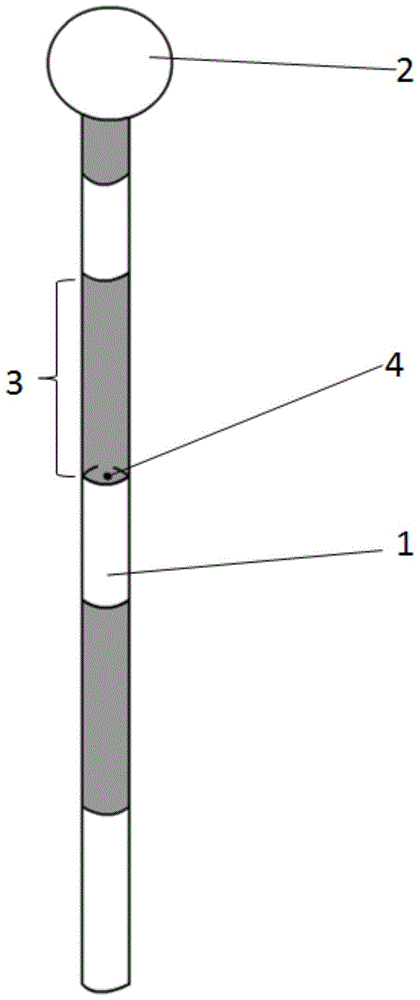
[0038] like figure 1 As shown, a coded measuring rod includes a control rod 1 and a spherical target 2 , the spherical target 2 is nested on the control rod 1 and can move up and down along the body of the control rod 1 .

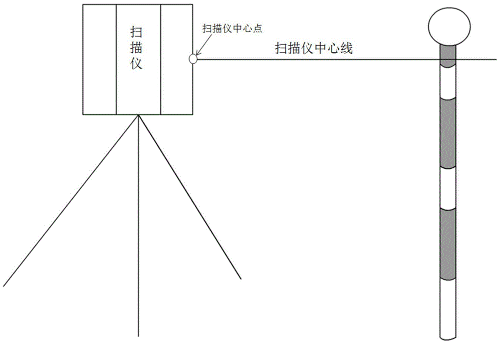
[0039] When in use, in the case of close-distance measurement or good visibility conditions, you can select the control mark 1 for measurement, or you can select the spherical target 2 for measurement, wherein the selection of the spherical target 2 for measurement is a prior art; For long-distance measurement or in the case of occlusion in the scene to be measured, since the spherical target 2 is easier to observe than the control mark 1, conventional methods can be used for measurement. At this...


PUM


Abstract

The invention relates to a coding measuring rod and a using method thereof. The coding measuring rod comprises a control marker rod and a spherical target which sleeves the control marker rod and is capable of moving up and down along the control marker rod, wherein the rod body of the control marker rod is divided into a plurality of sections of different lengths through paint of different colors or different materials. The coding measuring rod disclosed by the invention can be used for measuring of single scanner which can be used for observing the coding measuring rod for many times, and then comparing the data, and is applied to deformation monitoring; the coding measuring rod also can be used for a condition of measuring through a plurality of scanners, and is used for registering multi-station scanned data. The coding measuring rod can be used for solving the problem that a target plane visual angle is limited and a precision control problem for multi-time repeated observation; a working process of the scanners is combined to solve the control problem in practical measuring, register and compare the continuously observed point cloud data; the workload for distributing the target is reduced.

Description

technical field [0001] The invention relates to the technical field of surveying and mapping, in particular to a coded measuring rod and a using method thereof. Background technique [0002] The ground laser scanner is a surveying and mapping instrument that emits and receives laser signals for measurement. It is widely used in surveying and mapping, mining, urban, water conservancy, cultural conservation and other fields, and can quickly produce a large amount of high-precision point cloud data. [0003] When the terrestrial laser scanner collects data, similar to the traditional total station, it is necessary to set the scanning station, and then use the control point (or target) information to register the multi-site cloud data, so as to obtain the complete point of the measured target. cloud data. This process has become a standard process for terrestrial laser point cloud data collection. [0004] The existing point cloud scanning data registration method mainly uses ...

Claims


Application Information

Patent Timeline
Patent Type & Authority Patents(China)
IPC IPC(8): G01C15/08
CPCG01B11/16G01C15/08
Inventor 黄先锋张帆尹若捷
Owner 武汉大势智慧科技有限公司
Features
  • R&D
  • Intellectual Property
  • Life Sciences
  • Materials
  • Tech Scout
  • Unparalleled Data Quality
  • Higher Quality Content
  • 60% Fewer Hallucinations
Learn More