Supercharge Your Innovation With Domain-Expert AI Agents!

Multi-line laser radar obstacle avoidance device and method

A multi-line laser and lidar technology, applied in measurement devices, radio wave measurement systems, and electromagnetic wave re-radiation, etc., can solve problems such as increasing costs, increasing vehicle burden and energy consumption, and failing to detect obstacles, saving energy. Cost, solving the effect of limited top view angle and simple structure

Pending Publication Date: 2021-10-26
无锡太机脑智能科技有限公司
View PDF0 Cites 0 Cited by
  • Summary
  • Abstract
  • Description
  • Claims
  • Application Information

AI Technical Summary

Problems solved by technology

However, when the existing multi-line laser radar is in use, when the beam height of the laser radar is higher than the obstacle, the obstacle cannot be detected because the echo reflected from the obstacle is not received, that is, the laser radar blind spot
[0004] As a vehicle-mounted radar, when the vehicle uses laser radar for obstacle detection, it is not only necessary to detect obstacles at a long distance in front of the vehicle, but also to detect obstacles at short distances. Therefore, it is necessary to use multiple laser radars for detection. The detection method greatly increases the cost, and at the same time increases the vehicle burden and energy consumption. Therefore, a laser radar can provide short-range obstacle recognition and positioning capabilities without using multiple laser radars, and realize different distance detection through one laser radar. Obstacle detection, the emergence of radar obstacle avoidance devices that effectively solve the problem of limited viewing angles is imminent

Method used


Image

  • Multi-line laser radar obstacle avoidance device and method
  • Multi-line laser radar obstacle avoidance device and method
  • Multi-line laser radar obstacle avoidance device and method

Examples


Embodiment Construction

[0032] The following will clearly and completely describe the technical solutions in the embodiments of the present invention with reference to the accompanying drawings in the embodiments of the present invention. Obviously, the described embodiments are only some, not all, embodiments of the present invention. Based on the embodiments of the present invention, all other embodiments obtained by persons of ordinary skill in the art without creative efforts fall within the protection scope of the present invention.

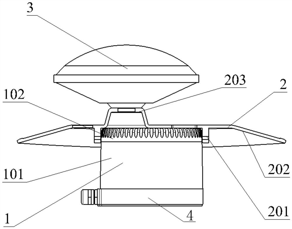
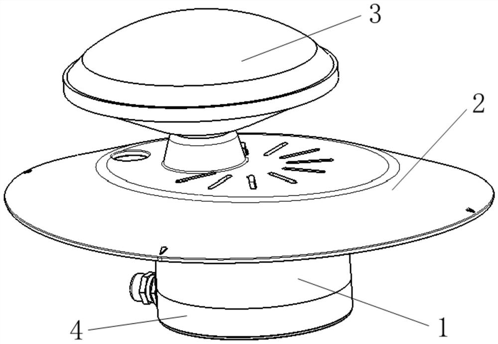
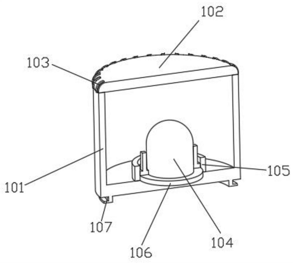
[0033] see Figure 1-6 , the present invention provides a technical solution: a multi-line laser radar obstacle avoidance device, including a laser radar 1 and a differential GPS antenna 3, the laser radar 1 is fixed on the upper end surface of the base 4, and the lid brim 2 is fixed on the upper end surface of the laser radar 1 , the visor 2 has a reflective structure that reflects the laser of the lidar 1, and the visor 2 increases the incident angle to the groun...


PUM


Abstract

The invention discloses a multi-line laser radar obstacle avoidance device and method in the field of vehicle-mounted sensor assemblys. The multi-line laser radar obstacle avoidance device is provided with a brim, the brim can reflect laser, after the laser is reflected through a reflecting film on the inner side wall of the brim, detection of obstacles at different distances by a laser radar is achieved, and the problem that the overlook angle is limited is effectively solved; the incident angle to the ground is increased through the brim, and the problem that a common laser radar is difficult to detect a cliff is solved. According to the invention, through the brim, the area in the scanning range becomes wider, the detection blind area of the laser radar is reduced, there is no need to add a plurality of radars to realize vehicle obstacle avoidance, and the cost is saved; due to the buckle type structure of the buckle on the brim, the brim is convenient to assemble and disassemble, when the obstacle avoidance distance needs to be adjusted, only the brim needs to be replaced, the structure is simple, and replacement is convenient; the differential GPS antenna mounting boss is arranged, so that a differential GPS antenna mounting position is reserved, and an antenna mounting scheme does not need to be specially designed for a vehicle.

Description

technical field [0001] The invention belongs to the field of vehicle sensor components; in particular, it relates to a multi-line laser radar obstacle avoidance device. Background technique [0002] Multi-line lidar uses time-of-flight measurements. Specifically: the laser radar sends out laser pulses and starts timing (t1). When the laser meets the target object and the light returns, the receiving end stops timing (t2), so that the distance can be obtained by the formula "distance = speed of light × (t2-t1) / 2" [0003] Multi-line lidar can also measure two or more distances and calculate their rate of change to obtain velocity. However, when the existing multi-line laser radar is in use, when the laser beam emitted by the laser radar is higher than the obstacle, the obstacle cannot be detected because the echo reflected from the obstacle is not received, that is, the laser radar blind spot. [0004] As a vehicle-mounted radar, when the vehicle uses lidar for obstacle de...

Claims


Application Information

Patent Timeline
Patent Type & Authority Applications(China)
IPC IPC(8): G01S17/931G01S17/86G01S7/481
CPCG01S17/931G01S17/86G01S7/481
Inventor 邵洪伟杨增辉
Owner 无锡太机脑智能科技有限公司
Features
  • R&D
  • Intellectual Property
  • Life Sciences
  • Materials
  • Tech Scout
  • Unparalleled Data Quality
  • Higher Quality Content
  • 60% Fewer Hallucinations
Learn More