Six-axis five-linkage spiral taper gear cutting machine tool

A technology for spiral bevel gears and processing machine tools, which is applied to metal processing machinery parts, metal processing, metal processing equipment, etc. It can solve the problems of large floor area, poor workmanship, and easy slipping of friction wheels, etc., and achieve equipment cost reduction , good process performance, the effect of good process performance

Inactive Publication Date: 2009-08-19
CHANGSHA HALIANG KAISHUAI PRECISION MASCH CO LTD
View PDF1 Cites 39 Cited by
  • Summary
  • Abstract
  • Description
  • Claims
  • Application Information

AI Technical Summary

Problems solved by technology

This treatment does not give full play to the role of numerical control technology, and there are the following main defects:
[0003] 1. There is a sector gear or friction wheel with a large diameter on the Z-axis sliding table 22 in the Z direction of the linear axis. The processing technology is not good, and the friction wheel is easy to slip;
[0004] 2. The shape of the workpiece box 28 is complicated, the manufacturability of the processing is not good, and it is difficult to ensure the processing accuracy;
[0005] 3. All the weight of the workpiece box 28 is pressed on the sector gear or the friction wheel, so it is difficult to unload;
[0006] 4. The X-axis sliding table 25 in the X direction of the linear axis is a gantry, and the Y-axis sliding table 24 in the Y direction of the linear axis moves vertically on the gantry. The servo motor and hydraulic balance cylinder are erected very high, and the protection is very difficult;
[0007] 5. For the sake of environmental protection and saving,

Method used


Image

  • Six-axis five-linkage spiral taper gear cutting machine tool
  • Six-axis five-linkage spiral taper gear cutting machine tool
  • Six-axis five-linkage spiral taper gear cutting machine tool

Examples


Embodiment Construction

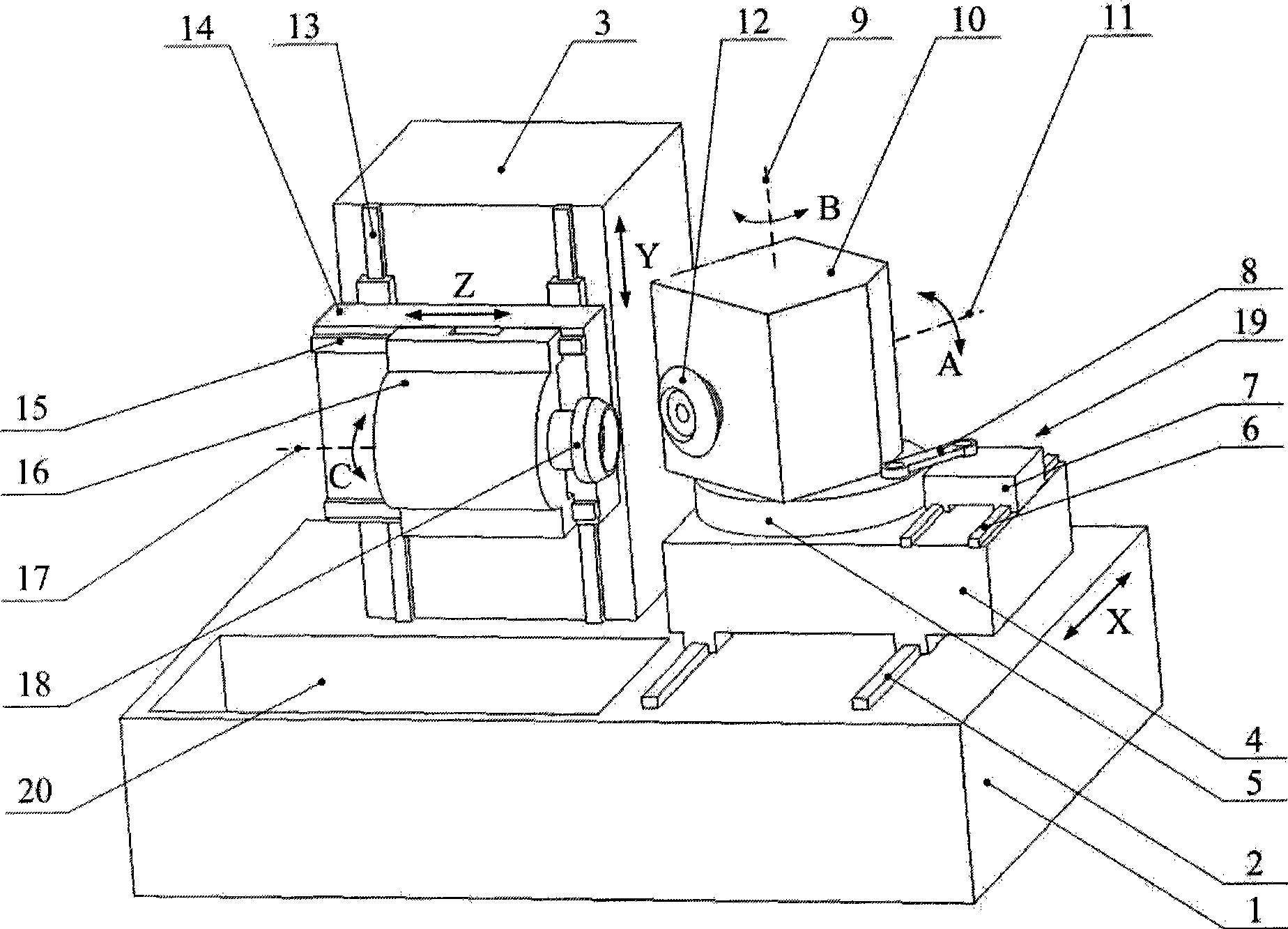
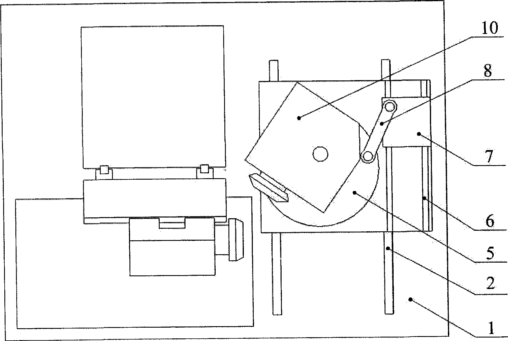
[0042] according to figure 2 and image 3 And the machine tool with the above structure has a bed 1, the top surface of the bed 1 is provided with a horizontal first X-direction linear guide rail 2 and a fixed column 3, and the first X-direction linear guide rail 2 is equipped with a The X-axis slide table 4 that moves along the first X-direction linear guide rail is provided with a turntable 5 and a turntable drive mechanism 19 that can rotate around the B-axis 9 perpendicular to the horizontal plane on the X-axis slide table 4, and is fixedly installed on the turntable The workpiece box 10 on the 5 is provided with a horizontal A-axis 11 that can be rotated under the driving mechanism, and one end of the A-axis 11 is equipped with a processed workpiece 12; The linear guide rail 2 is a vertical Y-direction linear guide rail 13, and the Y-direction linear guide rail 13 is equipped with a Y-axis slide 14 that can move along the Y-direction linear guide 13 under the drive of t...


PUM


Abstract

The invention relates to a six-axis five-linkage spiral bevel gear cutting machine. A lathe bed is provided with a fixed upright post and an X-direction linear guiderail with an X-axis slipway which is driven by a driving mechanism to move along the guiderail; the X-axis slipway is provided with a rotary table and a rotary table driving mechanism; the rotary table is provided with a workpiece box with a workpiece main shaft which is driven by the driving mechanism to rotate; one lateral surface of the upright post is provided with a Y-direction linear guiderail perpendicular to the X-direction linear guiderail; the Y-direction linear guiderail is provided with a Y-axis slipway which is driven by the driving mechanism to move along the guiderail; the Y-axis slipway is provided with a Z-direction linear guiderail perpendicular to the Y-direction linear guiderail; the Z-direction linear guiderail is provided with a tool box which is driven by the driving mechanism to move along the guiderail; and the tool box is provided with a rotatable tool spindle. The six-axis five-linkage spiral bevel gear cutting machine has the advantages of simple and stable structure, good reliability, good rigidity, few parts, small occupied area, easy protection and chip removal, and convenient assembly and disassembly of workpieces and tools.

Description

technical field [0001] The invention relates to numerical control processing equipment, and further refers to a gear milling machine and a gear grinding machine for processing spiral bevel gears. Background technique [0002] In the prior art, spiral bevel gear processing equipment includes mechanical spiral bevel gear processing machine tools and numerically controlled spiral bevel gear processing machine tools. The structure and adjustment links of mechanical spiral bevel gear processing machine tools are the most complicated among gear machine tools. With the advancement of technology, spiral bevel gear processing machine tools have adopted figure 1 As shown in the structure, it uses a computer to directly control three linear axes (namely X, Y, Z axes) and three rotational axes (namely A, B, C axes), that is, it can simulate the machining motion of a mechanical spiral bevel gear processing machine tool , so as to process the spiral bevel gear. The CNC spiral bevel gea...

Claims


Application Information

Patent Timeline
IPC IPC(8): B23F9/02B23F9/10B23Q1/26B23Q5/00
Inventor 殷俭王志永衣红
Owner CHANGSHA HALIANG KAISHUAI PRECISION MASCH CO LTD
Why Eureka
Try Eureka