Gear shifting manipulator

A manipulator and shift shaft technology, which is applied in the field of auto parts, can solve the problems that the deflection angle cannot be effectively excessive, affects the shifting efficiency and shifting feeling, and wears the locking area, so as to solve interference or abnormal friction, The effect of avoiding interference and facilitating effective return

Active Publication Date: 2015-06-10
SHIYAN DAFENG FLEXIBLE CONTROL CABLES
View PDF9 Cites 2 Cited by
  • Summary
  • Abstract
  • Description
  • Claims
  • Application Information

AI Technical Summary

Problems solved by technology

Although this invention can also realize the gear shift limit operation, the locking area has an integrated casting structure and is a spherical structure. This structural design is easy to make the locking element stuck on the side of the locking area after shifting and cannot be effectively returned. , at the same time, because the locking element has a certain deflection angle with the shift arm during the gear selection process, and the casting structure of the locking area cannot match the deflection with the shift arm. This deflection angle cannot be effectively transitioned. During the rotation process Unexpected wear will be caused to the locking area and locking elements; at the same time, when the manipulator is shifted back to neutral, the locking elements will not return to normal in time, and they will be stuck on the limit groove so that the neutral position cannot be found. Improved shift efficiency and shift feel

Method used


Image

  • Gear shifting manipulator
  • Gear shifting manipulator
  • Gear shifting manipulator

Examples


Embodiment Construction

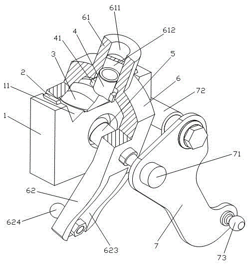
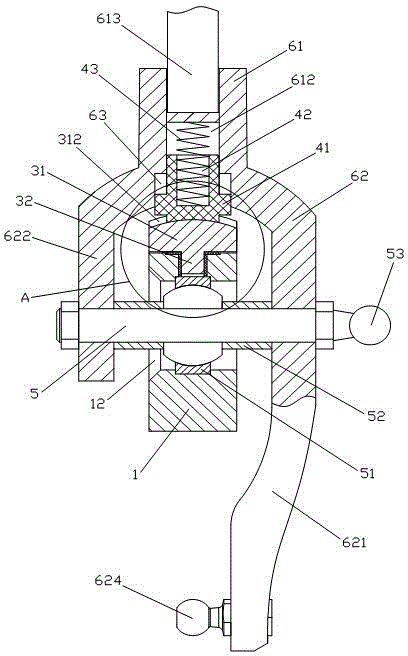
[0026] Such as Figures 1 to 6 As shown, the shift manipulator of the present invention includes a manipulator support 1, a shift limit pad 2, a shift limit block 3, a limit lock tongue 4, a shift shaft 5, a shift rocker arm 6 and a selector Gear rocker arm 7.

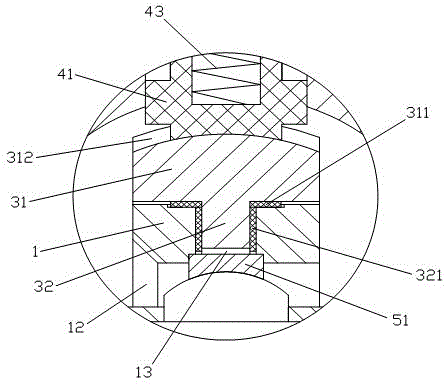
[0027] The manipulator support 1 has a block structure, and a pair of V-shaped grooves 11 are provided on the top. At the same time, the manipulator support 1 is horizontally provided with a bearing hole 12 from the middle of one side to the opposite side. The radial direction of the bearing hole 12 is provided with a limiting shaft hole 13, and one end of the bearing hole 12 has a slope; the pair of V-shaped grooves 11 are symmetrically located on both sides of the limiting shaft hole 13 and are close to the limiting shaft. One side of the hole 13 is provided with an elastic shift limit pad 2 .

[0028]The shift limit block 3 is movably installed on the top of the manipulator support 1, and it is composed of a trans...


PUM


Abstract

The invention relates to a gear shifting manipulator. The gear shifting manipulator comprises a manipulator support, a gear-shifting limit block, a limit bolt, a gear shifting shaft, a gear-shifting rocker arm and a shift-selecting rocker arm, wherein the gear-shifting limit block is movably mounted at the top end of the manipulator support, and consists of a transverse limit part and a longitudinal limit shaft; the gear-shifting rocker arm comprises a basis part and a connecting arm; a gear lever is arranged at the top end of the basis part in a penetrating manner; a bolt clamping groove is formed in the connection position of the basis part and the connecting arm; the limit bolt is provided with a cylindrical cavity, and the other end of the limit bolt is in contact connection with a neutral limit groove in a movable manner; a spring is embedded in the cylindrical cavity; one or more pairs of anti-rotation blocks are arranged on the limit bolt; the gear-shifting limit block collides with a gear-shifting limit blocking pad during forward shifting and backward shifting; one side of the upper end of the shift-selecting rocker arm is connected with a shaft body at one end of the gear shifting shaft in an assembled manner, and a rotating shaft of the gear-selecting rocker arm is fixedly arranged on the other side of the upper end of the shift-selecting rocker arm. The gear shifting manipulator disclosed by the invention has the advantages that the structural design is reasonable, the operation and the use are simple, the feeling of manipulation is good, gear selection and shifting are convenient and reliable, the out-of-gear problem after engagement of gears can be effectively avoided.

Description

technical field [0001] The invention belongs to the technical field of auto parts, and relates to a gear shift manipulator, in particular to a gear shift manipulator with a limit device that can effectively avoid problems such as disengagement of gears and failure to find a neutral gear after gears are engaged. Background technique [0002] Manual gear shift manipulators are generally not designed with shift manipulators. In actual use, manual gear shift manipulators, especially truck manual gear shift manipulators, often lose gear due to vehicle bumps and other reasons; It is difficult to find the neutral position due to the gear limit device. When changing gears, you need to shake the gear lever repeatedly to find the feeling and then change gears. The control feeling is very bad. [0003] The manual gear shift manipulator shakes the shift rocker arm left and right when selecting gears, and the gear selection rocker arm rotates around the gear selection rocker shaft throug...

Claims


Application Information

Patent Timeline
Patent Type & Authority Applications(China)
IPC IPC(8): F16H61/18F16H61/24
CPCF16H61/18F16H61/24
Inventor 余沿华
Owner SHIYAN DAFENG FLEXIBLE CONTROL CABLES
Why Eureka
Try Eureka