Ceiling air conditioner internal unit system

An indoor unit and ceiling-mounted technology for air conditioners, applied in air conditioning systems, heating methods, space heating and ventilation, etc., can solve problems such as poor thermal comfort, achieve space saving, good thermal comfort, and meet diverse needs.

Active Publication Date: 2015-06-10
GREE ELECTRIC APPLIANCES INC +1
View PDF6 Cites 8 Cited by
  • Summary
  • Abstract
  • Description
  • Claims
  • Application Information

AI Technical Summary

Problems solved by technology

[0003] The purpose of the present invention is to provide a ceiling-mounted air conditioner internal unit sy

Method used


Image

  • Ceiling air conditioner internal unit system
  • Ceiling air conditioner internal unit system
  • Ceiling air conditioner internal unit system

Examples


Example Embodiment

[0032] The embodiments of the present invention will be described in detail below with reference to the accompanying drawings, but the present invention can be implemented in a variety of different ways defined and covered by the claims.
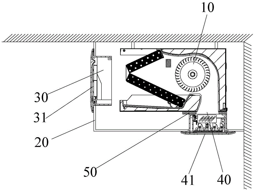
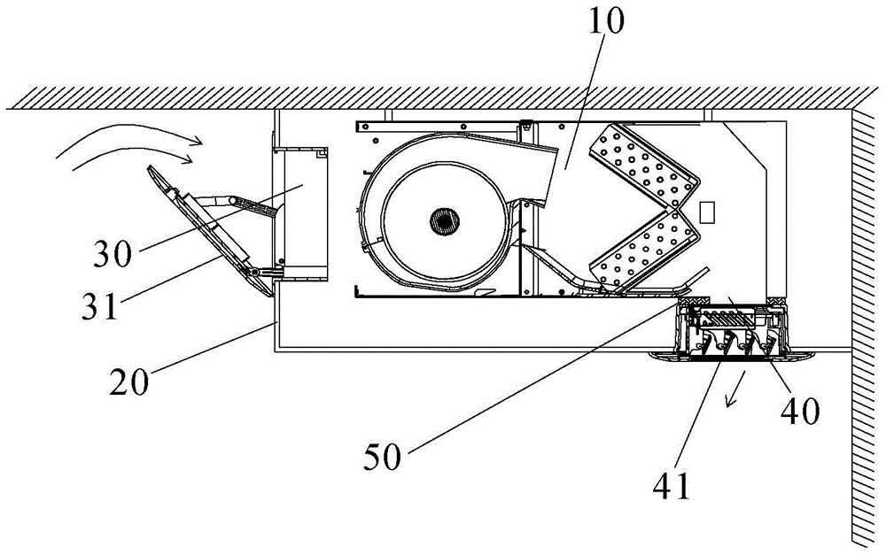
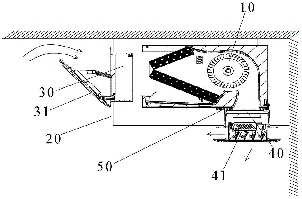
[0033] See Figure 1 to Figure 10 According to the ceiling-mounted air-conditioning internal unit system of the present invention, the indoor unit 10 is arranged in the ceiling 20, and further includes a return air outlet 30, which is arranged on the side of the ceiling, and the air outlet 40 is arranged on the bottom surface of the ceiling 20; A closeable air return device 31 is provided, and a closeable air outlet device 41 is provided at the air outlet 40. Set the direction of the air outlet to face the ground, so that the hot air can be sent to the lowest part of the room, which makes the room thermally comfortable, reduces the width of the ceiling 20, saves space, reserves more decoration space, and meets various requirements Demand.

[003...


PUM


Abstract

A ceiling-mounted air-conditioner indoor-unit system. An indoor-unit (10) is disposed inside a ceiling (20). The system further comprises: a return air inlet (30), disposed on a side surface of the ceiling (20); and a wind outlet (40), disposed on a bottom surface of the ceiling (20). A closeable return air inlet apparatus (31) is disposed at the return air inlet (30), and a closeable wind outlet apparatus (41) is disposed at the wind outlet (40).

Description

technical field [0001] The invention relates to the field of air conditioners, in particular to a ceiling-type air conditioner internal unit system. Background technique [0002] With the improvement of people's living standards, the requirements for decoration are getting higher and higher, and hidden air conditioners are becoming more and more popular. As a kind of hidden air conditioners, partial ceiling air conditioners can save more space than full ceiling air conditioners. The indoor units hidden in the partial ceiling in the existing market generally adopt the air circulation method of side return and side delivery or bottom return and side delivery. The installation height of the unit is about 2.8 meters. In this way, when the unit is heating, the hot air is sent to the side to follow the thermal expansion principle. The hot wind floats above the space, and it is difficult for the hot wind to reach the human activity area. The thermal comfort of the room is poor. I...

Claims


Application Information

Patent Timeline
IPC IPC(8): F24F1/00F24F13/06F24F1/0073
CPCF24F1/0047F24F13/06F24F1/0073F24F1/0025
Inventor 董明珠谭建明苏玉海杜辉王成雷新建周伙喜冯汇远赵成龙旷文琦陈泽波岳耀标林伟雪蔡勃李子颀章迎松潘亚前
Owner GREE ELECTRIC APPLIANCES INC
Why Eureka
Try Eureka