Unlock instant, AI-driven research and patent intelligence for your innovation.

Loading and unloading fixture

A technology of fixtures and clamping parts, which is applied in the field of loading and unloading fixtures for protective covers, and can solve the problems of high damage rate, difficult disassembly and time-consuming disassembly of protective covers and chip slots

Active Publication Date: 2017-08-08
INVENTEC PUDONG TECH CORPOARTION +1
View PDF3 Cites 0 Cited by
  • Summary
  • Abstract
  • Description
  • Claims
  • Application Information

AI Technical Summary

Problems solved by technology

[0005] The invention relates to a loading and unloading fixture, which is used to solve the problems of high damage rate, difficult disassembly and time-consuming disassembly of a protective cover and a chip slot

Method used


Image

  • Loading and unloading fixture
  • Loading and unloading fixture
  • Loading and unloading fixture

Examples


Embodiment Construction

[0058] The present invention will be described in further detail below in conjunction with the accompanying drawings and specific embodiments. The advantages and features of the present invention will become clearer from the following description. It should be noted that the drawings are all in a very simplified form and use imprecise ratios, which are only used to facilitate and clearly assist the purpose of illustrating the embodiments of the present invention.

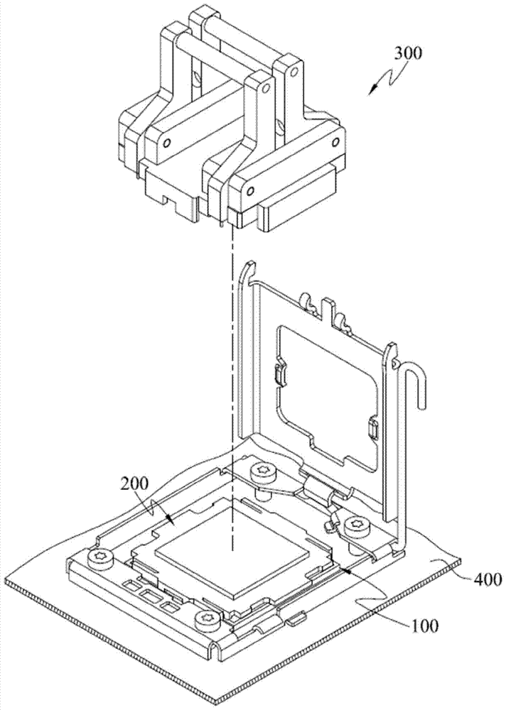
[0059] Please refer to Figure 1 to Figure 5 , figure 1 It is a three-dimensional structure schematic diagram of a mounting and dismounting fixture, a protective cover and a chip socket according to an embodiment of the present invention. figure 2 It is an exploded view of the three-dimensional structure of the protective cover and the chip socket according to an embodiment of the present invention. image 3 It is an exploded view of the three-dimensional structure of the loading and unloading fixture according ...


PUM


Abstract

A loading and unloading fixture is suitable for loading and unloading a protective cover. The protective cover includes a cover body and a plurality of fastening parts. There is a gap between the fastener and the cover. The loading and unloading fixture includes a fixing base and two clamping pieces. The fixing seat has a bottom surface and an accommodating space. The accommodating space is located on the bottom surface and is used for accommodating the protective cover. Each of the two clamping parts includes at least one pivotal part, a pressing part and at least one pushing part. The pressing portion and the pushing portion are respectively connected to two opposite ends of the pivotal portion. The pivot joint is pivotally arranged on the fixing base. The pushing parts protrude from the bottom surface and are respectively located on opposite sides of the accommodating space. When the cover body of the protective cover is located in the accommodating space, the pushing part is located in the gap, and the pressing part can move the pushing part away from or approach the accommodating space relatively, and make the pushing part drive the fastening part to move away from or approach the cover relatively .

Description

technical field [0001] The invention relates to a loading and unloading jig, in particular to a loading and unloading jig for loading and unloading a protective cover covering a chip slot. Background technique [0002] The surface of the printed circuit board is usually installed with many electronic components, expansion card slots and chip slots. When the printed circuit board is stored and transported, a protective cover is usually installed on the chip slot to prevent dust from entering into the chip slot where no chip is installed, causing the chip slot to fail. Wait until the chip is to be installed in the chip slot, and then remove the protective cover to insert the chip. [0003] The protective cover is usually fixed on the chip socket through a plurality of hooks. When installing the chip, the user must pull all the hooks at the same time, so that all the hooks are separated from the chip slot, and then the protective cover can be removed from the chip slot. [0...

Claims


Application Information

Patent Timeline
Patent Type & Authority Patents(China)
IPC IPC(8): H01R43/20H01R13/52
Inventor 张李锋
Owner INVENTEC PUDONG TECH CORPOARTION