Heat engine and thermodynamic cycle for converting heat into useful work

A heat engine and heat cycle technology, which is applied in the field of heat engines and heat cycles for converting heat into useful work, can solve the problems of reducing the degree of efficiency, not being able to be converted into mechanical work, and reducing the efficiency of internal combustion engines, etc., to achieve high The degree of efficiency, the effect of improving the degree of efficiency

Active Publication Date: 2015-06-10
I·马约罗斯
View PDF8 Cites 7 Cited by
  • Summary
  • Abstract
  • Description
  • Claims
  • Application Information

AI Technical Summary

Problems solved by technology

[0006] These devices have the disadvantage that the degree of efficiency of the internal combustion engine is reduced due to the fact that the waste heat of the exhaust gases (of the internal combustion engine) cannot be converted into mechanical work
On the other hand, heat engines include relatively complex mechanisms which cannot reproduce the ideal cycle, thereby also reducing the degree of efficiency

Method used


Image

  • Heat engine and thermodynamic cycle for converting heat into useful work
  • Heat engine and thermodynamic cycle for converting heat into useful work
  • Heat engine and thermodynamic cycle for converting heat into useful work

Examples


Embodiment Construction

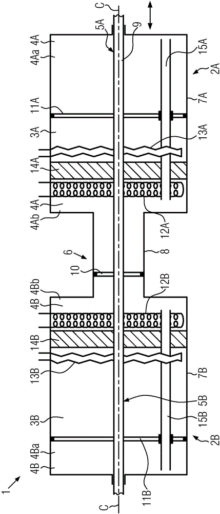
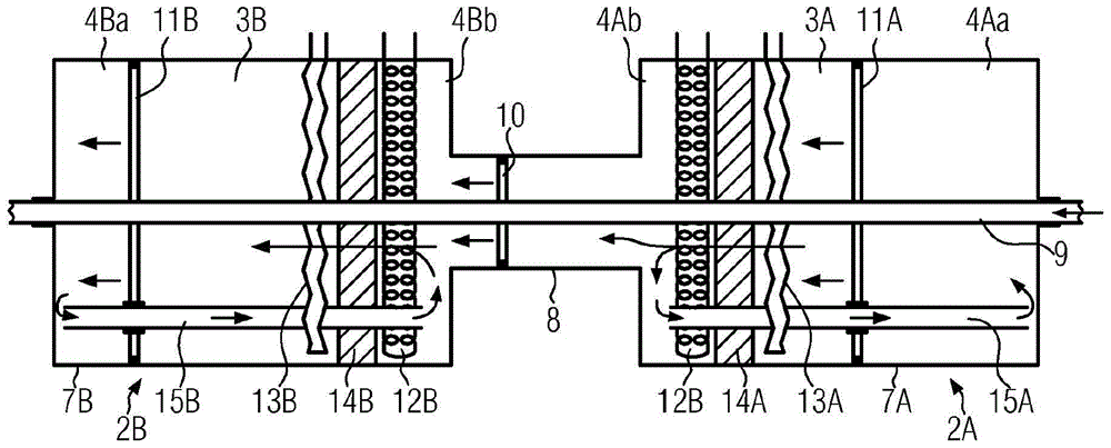
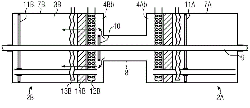
[0037] figure 1 A schematic diagram of a heat engine according to the invention is shown in side view. The first storage device 2A for working gas is in figure 1 , and is divided into a first cold chamber 3A and a first hot chamber 4A. Implemented by the first movable piston device 5A figure 1 in the division. The second storage means 2B is mirror-symmetrical to the first storage means 2A and is divided by a second movable piston means 5B into a second cold chamber 3B and a second hot chamber 4B. The two storage devices 2A, 2B are connected to each other via a connection 6 such that partial quantities of working gas can be exchanged between the two storage devices 2A, 2B during the configuration / constellation of the two piston devices 5A and 5B .

[0038] The two storage devices 2A, 2B are configured as displacement cylinders 7A, 7B with a circular cross-section and are divided into hot chambers 4A, 4B and cold chambers 3A, 3B, respectively. This division is achieved by ...


PUM


Abstract

Heat engine (1) for converting heat into useful work, comprising a first storage arrangement (2A) for a working gas, wherein said storage arrangement (2A) is divided into a first cold chamber (3A) and a first warm chamber (4A), and a first movable piston arrangement (5A) is configured in such a way that it changes the overall volume of the first storage arrangement (2A) and presses the working gas to and fro between the two first chambers (3A, 4A), characterized in that the heat engine (1) comprises a second storage arrangement (2B) for the working gas, wherein said second storage arrangement (2B) is divided into a second cold chamber (3B) and a second warm chamber (4B), and a second movable piston arrangement (5B) is configured in such a way that it changes the overall volume of the second storage arrangement (2B) and presses the working gas to and fro between the two second chambers (3B, 4B), and that a connection (6) between the first and the second storage arrangement (2A, 2B) is provided for a part quantity of the working gas to be exchanged between the two storage arrangements (2A, 2B) at least during a predefined constellation of the two piston arrangements (5A, 5B).

Description

technical field [0001] The invention relates to a heat engine and a thermodynamic cycle for converting heat into useful work according to the features of the preamble of solution 1 . Background technique [0002] Heat engines are typically used to convert heat into useful work that can be used, for example, to drive a generator or a vehicle. Fuel is burned inside or outside the heat engine and thereby converts the released thermal energy into mechanical work. [0003] Internal combustion engines represent a class of heat engines. A mixture of air and fuel is present in the cylinders of a diesel engine, for example, so that it is naturally compressed by the piston with great force. The energy thus released expands the gas and thus causes a force to act on the piston, which can then perform mechanical work. After completion of gas expansion, the gas is exhausted into the environment as waste gas, the waste heat contained in the gas not being used anymore. [0004] Other re...

Claims


Application Information

Patent Timeline
Patent Type & Authority Applications(China)
IPC IPC(8): F02G1/043
CPCF02G1/043F02G1/0445F02G1/055
Inventor I·马约罗斯
Owner I·马约罗斯
Why Eureka
Try Eureka