
Method and apparatus for controlling heating of fuel filter

A fuel filter and controller technology, applied in fuel heat treatment devices, chemical instruments and methods, filtration and separation, etc., to reduce cost and weight, improve reliability and accuracy

Inactive Publication Date: 2015-06-17
HYUNDAI MOTOR CO LTD
View PDF0 Cites 3 Cited by
  • Summary
  • Abstract
  • Description
  • Claims
  • Application Information

AI Technical Summary

Problems solved by technology

[0009] However, a problem with the disclosed heating device is that when the vehicle is driven and restarted, the fuel filter is still heated by the logic even when it is not required to heat the fuel filter

Method used


Image

  • Method and apparatus for controlling heating of fuel filter
  • Method and apparatus for controlling heating of fuel filter
  • Method and apparatus for controlling heating of fuel filter

Examples


Embodiment Construction

[0030] Reference will now be made in detail to various embodiments of the invention, examples of which are illustrated in the accompanying drawings and described below. While the invention has been described in conjunction with exemplary embodiments, it will be understood that present description is not intended to limit the invention to those exemplary embodiments. On the contrary, the invention is intended to cover not only the exemplary embodiments, but also alterations, modifications, equivalents and other embodiments as included within the spirit and scope of the invention as defined by the claims.

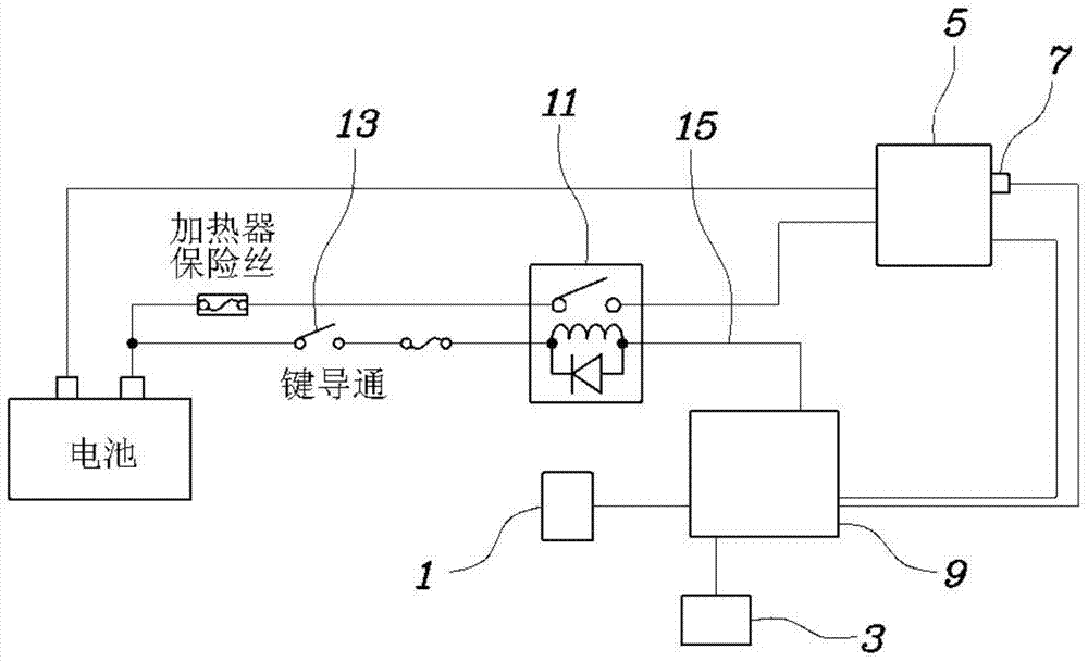
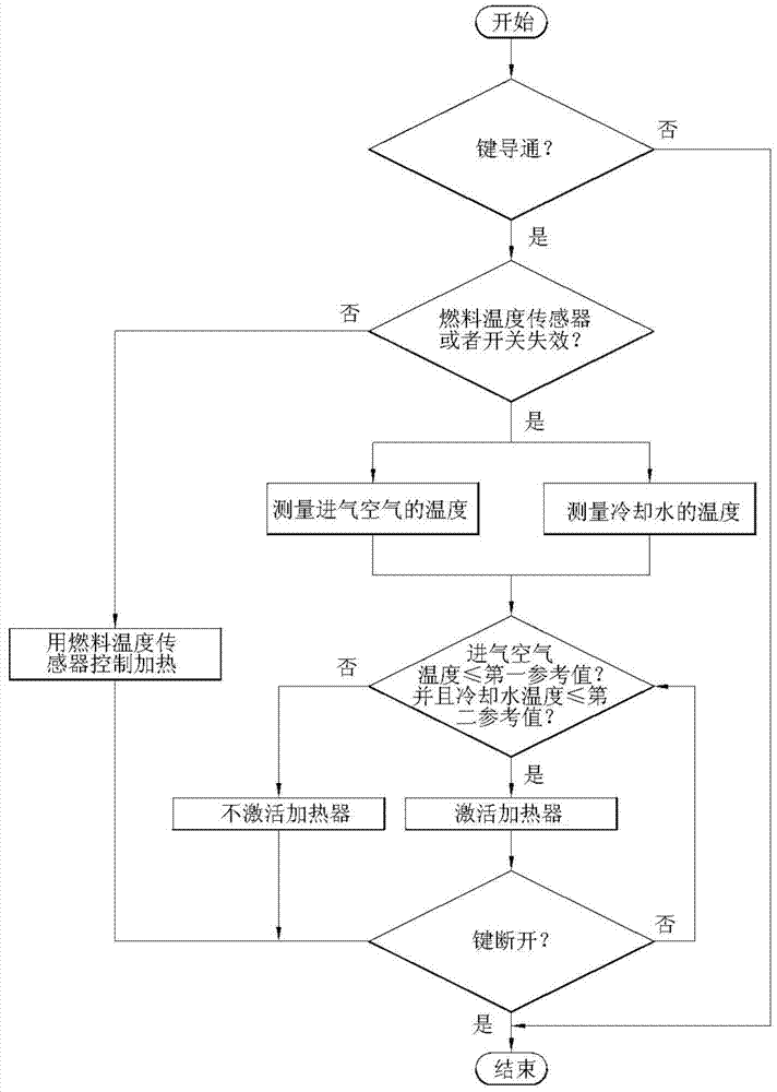
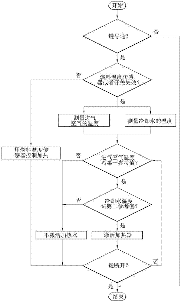
[0031] figure 1 is a block diagram of an apparatus for controlling heating of a fuel filter according to various embodiments of the invention, figure 2 is a flowchart of a method of controlling heating of a fuel filter according to a first embodiment of the present invention, image 3 is a flowchart of a method of controlling heating of a fuel filter according to a second...


PUM


Abstract

Disclosed are a method and an apparatus for controlling heating of a fuel filter. The method may include a first step of measuring a temperature of intake air that enters an engine, a second step of measuring a temperature of cooling water, and a third step of, upon input of a key-on signal, controlling whether to activate or deactivate a heater for the fuel filter in response to the measured temperatures of the intake air and the cooling water.

Description

technical field [0001] In general, the present invention relates to a technique for controlling heating of a fuel filter, and more particularly, to a method and apparatus for controlling heating of a fuel filter using an A temperature sensor instead of a fuel temperature sensor in the fuel filter implements the heating logic for the fuel filter. Background technique [0002] Generally, in a fuel filter for a vehicle in a cold environment, such as in winter, fuel may undergo solidification due to cold air to clog the fuel filter, resulting in a failure to start or an engine stop. Therefore, in order to prevent such a problem, a control action for heating the fuel filter is required. [0003] A conventional solution is to have a thermostat in the fuel filter so the heater operates in response to temperature. However, if the thermostat malfunctions or malfunctions, there can be problems with starting performance, such as a failed start or engine stalling. [0004] To solve t...

Claims


Application Information

Patent Timeline
Patent Type & Authority Applications(China)
IPC IPC(8): F02M37/22F02M31/125
CPCF02M31/125F02M37/30B01D35/005B01D35/18
Inventor 朴秀永金兑映
Owner HYUNDAI MOTOR CO LTD
Learn More