A monitoring method based on time-triggered Ethernet

A time-triggered, Ethernet technology, applied in the field of communication, can solve the problems such as the inability to meet the monitoring requirements of high-reliability switching networks, the inability to realize the monitoring of data flow information and time information, and achieve the effect of meeting the monitoring requirements.

Active Publication Date: 2018-07-03
AVIC NO 631 RES INST
View PDF3 Cites 0 Cited by
  • Summary
  • Abstract
  • Description
  • Claims
  • Application Information

AI Technical Summary

Problems solved by technology

[0002] The existing Ethernet simply monitors all messages and cannot meet the monitoring requirements of a highly reliable switching network
For time-triggered Ethernet, monitoring of data flow information and time information cannot be realized

Method used


Image

  • A monitoring method based on time-triggered Ethernet
  • A monitoring method based on time-triggered Ethernet

Examples


Embodiment Construction

[0020] In time-triggered Ethernet, the guardianship function should reside on the switch so that the guardianship can shut down the inputs and outputs of the switch. The guardian has its own time synchronization algorithm and is able to receive all messages coming into the switch.

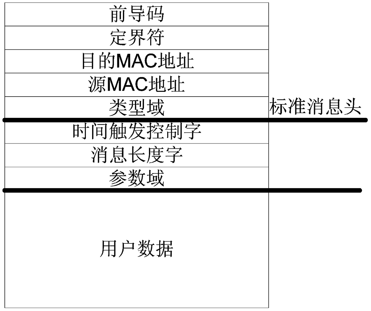
[0021] A typical frame format includes a preamble, a fixed field, a destination MAC address, a source MAC address, a type field, and the like. The time-triggered message further includes a time-triggered control word, a message length, a parameter field, and the like. Messages are divided into time-triggered messages, protocol control messages, and rate-limited messages through type field information. The time trigger message format is as follows figure 1 shown.

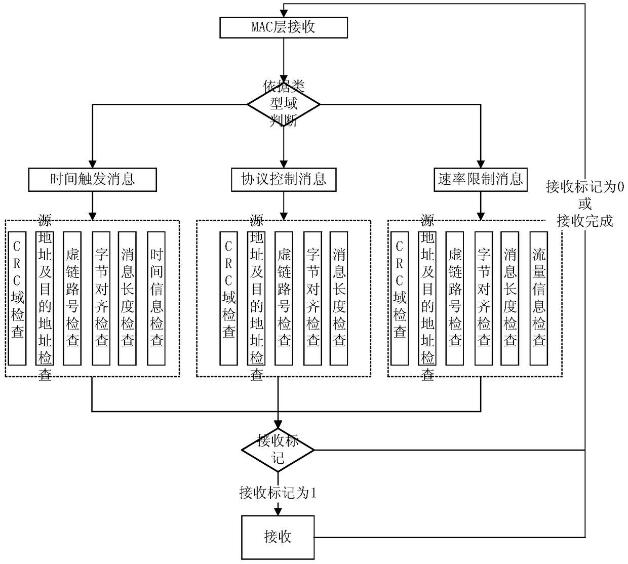
[0022] A monitoring method based on time-triggered Ethernet, see figure 2 ,described as:

[0023] 1] Perform register configuration first, including configuration of source address register, destination address register, virtual lin...


PUM


Abstract

The invention provides a time-triggered Ethernet monitoring method. Addressed guardian issues with time-triggered communications. A monitoring method based on time-triggered Ethernet, which divides the messages passing through the MAC layer into time-triggered messages, protocol control messages, and rate limit messages, respectively checks and filters each message, and then filters the messages that meet the check items. The message is submitted to the switching module for switching. The invention realizes the monitoring of time trigger messages, protocol control messages and rate limiting messages, and can meet the monitoring requirements of highly reliable switching networks.

Description

technical field [0001] The invention belongs to the communication field and relates to a time-triggered Ethernet monitoring method. Background technique [0002] The existing Ethernet simply monitors all messages and cannot meet the monitoring requirements of a highly reliable switching network. For time-triggered Ethernet, monitoring of data flow information and time information cannot be realized. [0003] Therefore, it is necessary to propose a monitoring design method, which can realize the monitoring function residing on the switch in the time-triggered Ethernet. Contents of the invention [0004] The purpose of the present invention is to provide a monitoring method based on time-triggered Ethernet, to check the messages passing through the switch in the network, and the wrong messages will be discarded. [0005] Technical solution of the present invention is: [0006] A monitoring method based on time-triggered Ethernet, which is special in that it includes the f...

Claims


Application Information

Patent Timeline
Patent Type & Authority Patents(China)
IPC IPC(8): H04L12/26
Inventor 田园黄韬王红春李大鹏陈长胜何向栋李玉发蒲恺
Owner AVIC NO 631 RES INST
Why Eureka
Try Eureka