Electrically simulated inertial friction welding method

A friction welding and electrical simulation technology, applied in welding equipment, non-electric welding equipment, metal processing equipment, etc., can solve the problems of difficult control of different mechanical inertias, improve welding efficiency, eliminate inertia levels, and reduce tedious manual labor. Effect

Inactive Publication Date: 2016-09-21
NORTHWESTERN POLYTECHNICAL UNIV
View PDF7 Cites 0 Cited by
  • Summary
  • Abstract
  • Description
  • Claims
  • Application Information

AI Technical Summary

Problems solved by technology

[0005] In order to overcome the deficiency that the existing friction welding method adopts different mechanical inertias and is difficult to control, the present invention provides an electrical analog inertia friction welding method

Method used


Image

  • Electrically simulated inertial friction welding method

Examples


Embodiment Construction

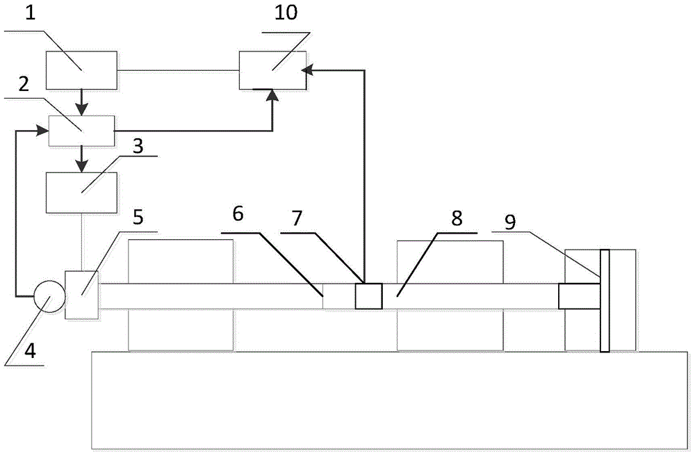
[0017] refer to figure 1 . The specific steps of the electric simulation inertial friction welding method of the present invention are as follows:

[0018] Before friction welding, inertial friction welding parameters, such as initial rotational speed, required inertia, friction pressure, upsetting pressure, etc., are stored in the computer 1 . Among them, the initial speed is 800~2000r / min, and the required inertia is 5~50kg m 2 , The friction pressure is 2~10MPa, and the upsetting pressure is 4~20MPa. After the friction welding blank is put in, the automatic welding process is started, the welding blank is clamped by the fixture, and the moving end 8 is driven by the hydraulic cylinder 9 to fast forward, work forward, pre-jack, and retreat for a certain distance and then stop. The main shaft 5 is driven and accelerated by the DC motor 3 under the control of the DC governor 2. When the speed of the main shaft 5 reaches the set initial speed value of 800-2000r / min, it rotat...


PUM


Abstract

The invention discloses an electric simulation inertia friction welding method used for solving the technical problem that according to an existing friction welding method, different mechanical inertias are adopted and difficult to control. According to the technical scheme, output rotation speed and torque are calculated according to the inertia required by welding and collected speed and angular speed, an output rotation speed or torque instruction is sent to a direct-current speed regulator, output torque of a direct-current motor is adjusted by changing armature voltage and armature current of the direct-current motor, rotation speed of a main shaft is controlled, and accordingly the change rule of the rotation speed of the main shaft and the rotation speed change rule under the same friction resistance torque and mechanical inertia condition are the same. Compared with the prior art, the mode that the mechanical inertias are simulated through electric inertia replaces the mode that flywheel discs are combined in an existing inertia friction welding machine to obtain different mechanical inertias, inertia stage difference is eliminated, tedious physical labor brought due to the fact that inertia flywheels are detached and adjusted repeatedly is reduced, and stepless continuous adjustment of the inertias is achieved. Welding efficiency is improved, and welding machine cost is lowered.

Description

technical field [0001] The invention relates to a friction welding method, in particular to an electrical simulation inertial friction welding method. Background technique [0002] Inertial friction welding is a technology that utilizes the kinetic energy pre-stored in the rotating flywheel for welding. Traditional inertial friction welding machines generally use a combination of flywheel discs of different sizes to obtain different mechanical inertias. See Spindler D.E. published in "Welding" in 1994 Journal", Vol. 73, No. 3, pp. 37-42, "What industry needs to know about friction welding". Before welding, first fix the required flywheel on the rotating spindle. Flywheels generally have three groups with different inertias, and different combinations can obtain 8 groups of different inertias. During welding, the workpiece on one side is connected to the flywheel, while the rotational freedom of the workpiece on the other side is constrained. The flywheel is accelerated to...

Claims


Application Information

Patent Timeline
Patent Type & Authority Patents(China)
IPC IPC(8): B23K20/12
CPCB23K20/122B23K20/123
Inventor 杜随更
Owner NORTHWESTERN POLYTECHNICAL UNIV
Why Eureka
Try Eureka