
A lamp device

A technology for equipment and desk lamps, applied in the field of LED desk lamps and desk lamp equipment, can solve problems such as slowness, inability to change the angle, and failure to maintain it

Inactive Publication Date: 2017-09-01
SHANGHAI MEIDIXIN ELECTRONICS TECH
View PDF5 Cites 0 Cited by
  • Summary
  • Abstract
  • Description
  • Claims
  • Application Information

AI Technical Summary

Problems solved by technology

In the prior art, the support angle in the herringbone support structure is fixed, that is to say, the support angle between the two cannot be adjusted
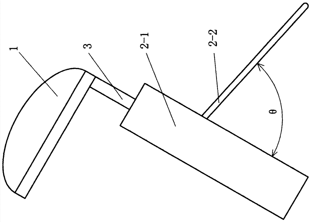
[0004] Another situation of the desk lamp in the prior art is that the support plate can be rotated. When not in use, the support plate is rotated and folded for storage, and the support plate is unfolded when in use; however, the support plate in the unfolded state, it and The angle formed between the base bodies has only one stable angle, such as figure 1 The stable angle shown in is θ, and this stable state is determined by its structure; if the user adjusts the angle to an angle smaller than θ, the desk lamp is in an unstable state, and under the action of gravity, the support plate will immediately Or turn slowly by itself, the height of the desk lamp drops, and finally stabilizes at the angle of θ
When the desk lamp is in an unstable state, it cannot maintain or maintain the current angle state for a long time because of the lack of structural support
[0005] To sum up, in the desk lamp of the prior art, a herringbone support structure is formed between the support plate and the base body, and the structure has only a fixed angle, which cannot be adjusted, that is, the size of the angle cannot be changed
Therefore, this situation causes inconvenience in use

Method used


Image

  • A lamp device
  • A lamp device
  • A lamp device

Examples


Embodiment 1

[0155] use figure 1 and figure 2 Shown the product of prior art, it is transformed, updated with the technology of the present invention.

[0156] This embodiment further describes, illustrates and introduces the invention according to five parts including component manufacturing, product assembly, product use, adjustment principle and points for attention.

[0157] 1. Parts manufacturing

[0158] 1. Manufacture the upper structure in the support plate 2-2, such as Figure 34 to Figure 40 shown.

[0159] Figure 34 It is a schematic diagram of the upper structure; the upper structure includes an L-shaped upper left structure, an inverted L-shaped upper right structure and a connecting block. Figure 35 yes Figure 34 left view of . Figure 36 yes Figure 34 E-E in the sectional view. Figure 37 yes Figure 34 The F-F in the sectional view. Figure 38 yes Figure 34 top view. Figure 39 yes Figure 34 bottom view. Figure 40 It is a three-dimensional schematic d...

Embodiment 2

[0200] In Embodiment 1, there are five first bar-shaped protrusions T on the cover body 52; five second bar-shaped protrusions T are also arranged on the pressing block 53, and they and the five first bar-shaped protrusions T on the cover body Shaped protrusion T is the corresponding setting.

[0201] In this embodiment, the five first bar-shaped protrusions T on the cover body 52 are changed to five outer arc-shaped protrusions TY; the outer arc-shaped protrusions TY are distributed in a fan shape; the fan-shaped circle center, It is located on the extension line of the center line of the rotation hole ZK adjacent to the cover body 52 and the base 51 . The situation of five outer arc-shaped protrusions on the cover body 52 is shown in Figure 33 As shown; each outer arc-shaped protrusion is actually a small part of the sphere.

[0202] At the same time, in the present embodiment, the five second bar-shaped protrusions t on the pressing block 53 are changed into five inner a...

Embodiment 3

[0208] combine Figure 39 Be explained.

[0209] In this embodiment, the cover body 52 is provided with 105 first arc-shaped protrusions 52-1. Each first arc-shaped protrusion 52-1 is a part of a small sphere, or in other words, a part of a small sphere constitutes a first arc-shaped protrusion 52-1. The inner side of the briquetting block 53 is flat and free of protrusions.

[0210] The vertical round rod body of the support plate is clamped between the first arc-shaped protrusion 52-1 of the briquetting block 53 and the cover body 52, that is to say, on one side, the vertical round bar body of the support plate is subjected to the briquetting block 53 On the other side, the vertical round rod body of the support plate is pressed by the first arc-shaped protrusion 52-1 on the cover body 52.

[0211] The user of the desk lamp needs to apply a certain driving force to make the vertical round rod body of the support plate rotate; if there is no driving force or the driving fo...


PUM


Abstract

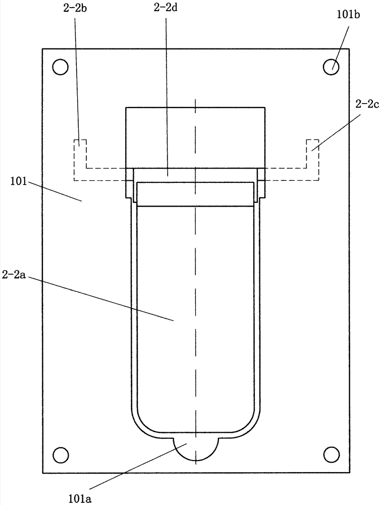
The invention relates to the technical field of lamps and discloses a table lamp device; in order to solve the problem that the support angle cannot be adjusted, a technical proposal is proposed. It is characterized in that: the support plate (2-2) includes an upper structure and a lower plate (2-2a); the upper structure includes a left upper structure (2-2b), a right upper structure (2-2c) and a connecting block (2 ‑2d); the upper structure (2‑2b) includes vertical and transverse round rods; the bottom of the connection block (2‑2d) is arc-shaped, and the bottom is groove-shaped; the lower plate (2‑2a ) top is a hollow-out structure, its bottom is arc-shaped, and above it is a bump shape; a base (51), a cover (52) and a pressing block (53) are set on the back plate (101); on the cover (52 ) and the base (51) are provided with a rotating hole (ZK); the upper structure, its vertical round rod body is located in the gap between the pressure block (53) and the cover body (52), and its horizontal round rod body passes through Through the turning hole (ZK). The beneficial effect is that the support angle can be adjusted and the like.

Description

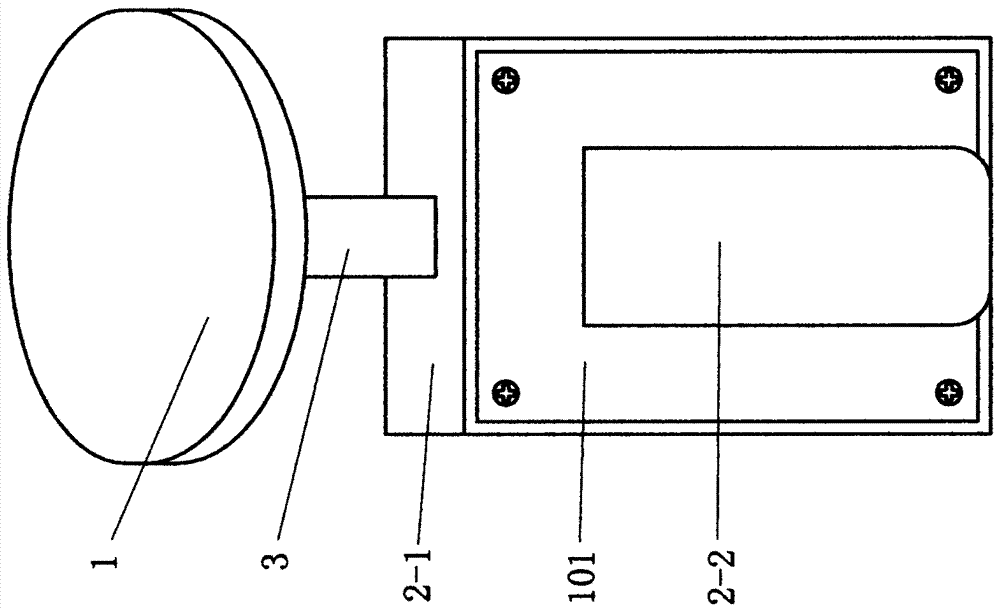
technical field [0001] The invention relates to the technical field of lamps, in particular to a desk lamp device; the technology of the invention is especially suitable for LED desk lamps. Background technique [0002] Among the desk lamps of the prior art, there is a kind of desk lamp that includes a lamp cap, a rod body, and a base; and the base includes an inclined base body and a support plate; glyph support structure, such as figure 1 shown; figure 2 yes figure 1 right view of . exist figure 1 and figure 2 Middle: Number 1 is the lamp holder; Number 2-1 is the main body of the base; Number 2-2 is the support plate; Number 3 is the rod body; Number 101 is the back plate; θ is the support angle. [0003] A herringbone support structure is formed between the support plate and the base body. In the prior art, the support angle in the herringbone support structure is fixed, that is to say, the support angle between the two cannot be adjusted. [0004] Another situ...

Claims


Application Information

Patent Timeline
Patent Type & Authority Patents(China)
IPC IPC(8): F21S6/00F21V21/14F21Y115/10
Inventor 张汉平梁怀清
Owner SHANGHAI MEIDIXIN ELECTRONICS TECH
Learn More