A tower crane slewing mechanism eddy current braking system

A technology of slewing mechanism and eddy current braking, which is applied in the direction of cranes, load hanging components, transportation and packaging, etc. It can solve problems such as damage to the slewing mechanism of the tower crane, severe shaking of the tower crane fuselage, impact on the steel structure, etc., and achieve optimal braking effect of effect

Active Publication Date: 2017-01-04
SHENZHEN INVT ELECTRIC
View PDF6 Cites 0 Cited by
  • Summary
  • Abstract
  • Description
  • Claims
  • Application Information

AI Technical Summary

Problems solved by technology

[0002] Tower crane is a commonly used lifting equipment on construction sites. Due to the long tower arm, the slewing mechanism of the tower crane has a large inertia. When shifting gears (including acceleration and deceleration) and parking, especially when suddenly stopping at a high-end position, the tower crane will The shaking of the body is quite severe, and the tower arm will bounce back and forth to produce an impact on the steel structure. This impact will cause certain damage to the slewing mechanism of the tower crane.
[0003] The traditional solution can only provide eddy current braking voltage (which can be called eddy current voltage or eddy current output voltage) to the eddy current coil (ie, electromagnetic brake) of the eddy current motor of the slewing mechanism of the tower crane to brake the eddy current motor when parking, and the eddy current braking The voltage is selected through the limited taps of the transformer, so the best braking effect cannot be achieved when parking, and the smooth running effect cannot be achieved due to the impact of inertial impact when shifting gears

Method used


Image

  • A tower crane slewing mechanism eddy current braking system
  • A tower crane slewing mechanism eddy current braking system
  • A tower crane slewing mechanism eddy current braking system

Examples


Embodiment Construction

[0032] The following will clearly and completely describe the technical solutions in the embodiments of the present invention with reference to the accompanying drawings in the embodiments of the present invention. Obviously, the described embodiments are only some, not all, embodiments of the present invention. Based on the embodiments of the present invention, all other embodiments obtained by persons of ordinary skill in the art without making creative efforts belong to the protection scope of the present invention.

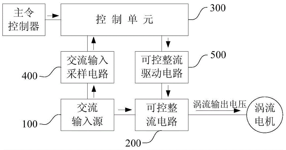
[0033] see figure 1 , the embodiment of the present invention discloses an eddy current brake system of the slewing mechanism of the tower crane, to buffer the impact of the tower crane when shifting gears, and achieve better running and braking effects, including:

[0034] The AC input source 100, the controllable rectification circuit 200 connected between the AC input source 100 and the eddy current coil of the eddy current motor, and the control unit 300 c...


PUM


Abstract

The invention discloses an eddy current braking system of a tower crane swing mechanism. The eddy current braking system comprises an alternating-current input source, a controlled rectifier circuit, a control unit, an alternating-current input sampling circuit and a controlled rectifier driving circuit, wherein the controlled rectifier circuit is connected between the alternating-current input source and an eddy current coil; the control unit is connected with a master controller of a tower crane; the alternating-current input sampling circuit is connected between the control unit and the alternating-current input source; the controlled rectifier driving circuit is connected between the control unit and the controlled rectifier circuit; the controlled rectifier driving circuit is used for driving the controlled rectifier circuit according to PWM (Pulse-Width Modulation) sent by the control unit; the control unit is used for calculating the PWM according to a swing speed gear given by the master controller and the alternating-current input voltage and phase which are sampled by the alternating-current input sampling circuit, so as to buffer impact generated when the tower crane is subject to gear shifting and achieve optimal operating and braking effects.

Description

technical field [0001] The invention relates to the technical field of eddy current motor control of the slewing mechanism of the tower crane, and more specifically, relates to an eddy current brake system of the slewing mechanism of the tower crane. Background technique [0002] Tower crane is a commonly used lifting equipment on construction sites. Due to the long tower arm, the slewing mechanism of the tower crane has a large inertia. When shifting gears (including acceleration and deceleration) and parking, especially when suddenly stopping at a high-end position, the tower crane will The body shakes quite severely, and the tower arm will bounce back and forth to produce an impact on the steel structure. This impact will cause certain damage to the slewing mechanism of the tower crane. [0003] The traditional solution can only provide eddy current braking voltage (which can be called eddy current voltage or eddy current output voltage) to the eddy current coil (ie, elec...

Claims


Application Information

Patent Timeline
Patent Type & Authority Patents(China)
IPC IPC(8): B66C23/86
CPCB66C13/30B66C23/84B66C2700/082
Inventor 罗云
Owner SHENZHEN INVT ELECTRIC
Why Eureka
Try Eureka