
Three-dimensional strain tensor change observing method

A strain tensor, three-dimensional technology, used in measuring devices, instruments, etc., to achieve the effect of convenient self-inspection

Inactive Publication Date: 2015-07-01
NAT INST OF NATURAL HAZARDS MINISTRY OF EMERGENCY MANAGEMENT OF CHINA +1
View PDF3 Cites 4 Cited by
  • Summary
  • Abstract
  • Description
  • Claims
  • Application Information

AI Technical Summary

Problems solved by technology

[0012] However, how to observe the change of the three-dimensional strain tensor is still an unresolved problem

Method used


Image

  • Three-dimensional strain tensor change observing method
  • Three-dimensional strain tensor change observing method
  • Three-dimensional strain tensor change observing method

Examples


specific Embodiment

[0039] Utilize 9 wire strain sensors, arranged in the following way:

[0040] Establish a Cartesian coordinate system XYZ;

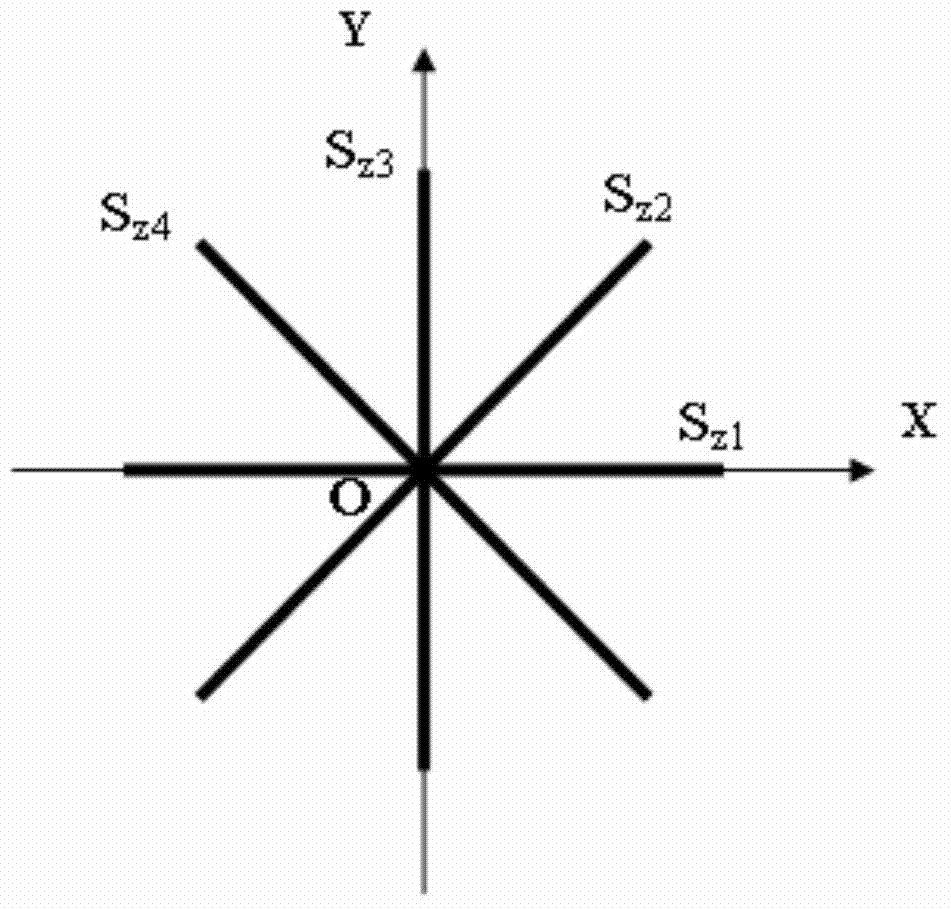
[0041] Arrange 4 linear strain sensors in the XY plane, and observe the linear strain s in 4 directions at equal intervals of 45° z1 , s z2 , s z3 and s z4 , where s z1 and s z3 Coincident with the X-axis and Y-axis respectively (attached figure 1 );

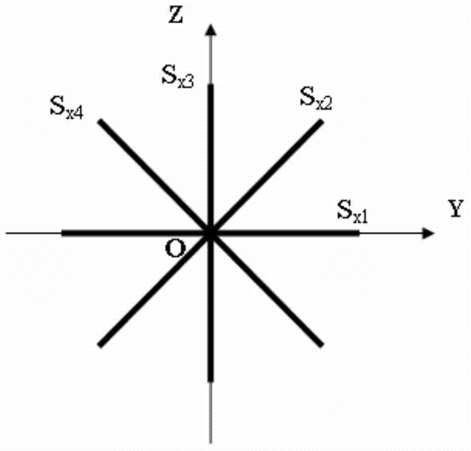
[0042] Arrange 4 linear strain sensors in the YZ plane, and observe the linear strain s in 4 directions at equal intervals of 45° x1 , s x2 , s x3 and s x4 , where s x1 and s x3 Coincident with the Y-axis and Z-axis respectively (attached figure 2 ).

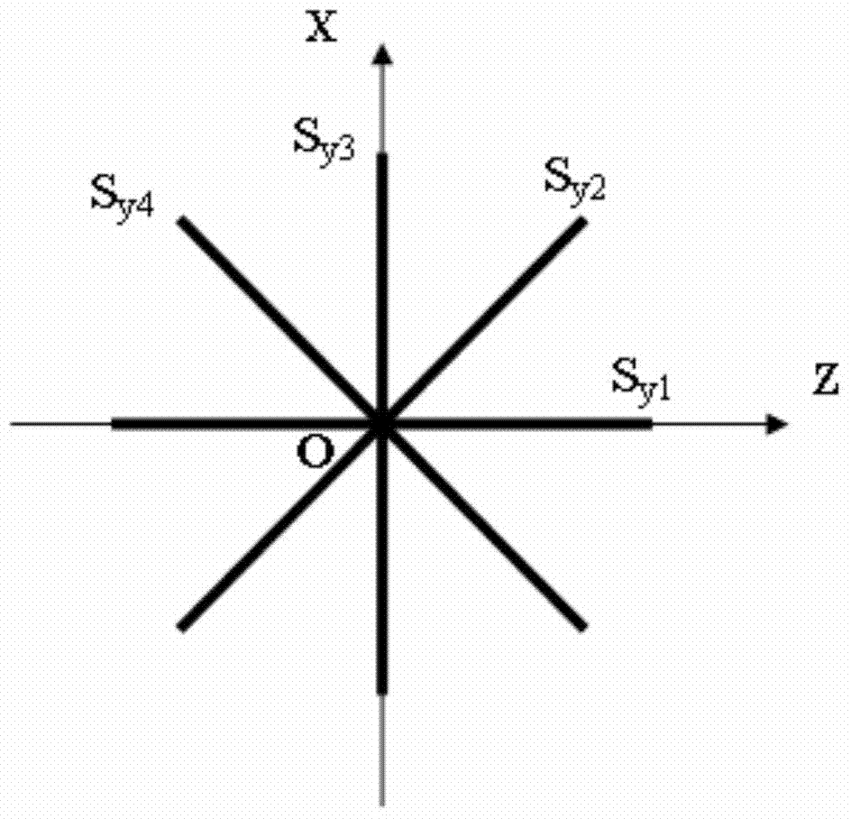
[0043] Arrange 4 linear strain sensors in the ZX plane, and observe the linear strain s in 4 directions at equal intervals of 45° y1 , s y2 , s y3 and s y4 , where s y1 and s y3 Coincident with the Z axis and X axis respectively (attached image 3 );

[0044] In fact, there are only 9 line strain observations, and the following equival...


PUM


Abstract

The invention discloses a three-dimensional strain tensor change observing method. The three-dimensional strain tensor change observing method includes the steps that a plurality of linear strain sensors are respectively distributed in three planes which are perpendicular to one another; linear strain changes in four directions in each plane are observed, wherein every two adjacent observing directions are spaced by 45 degrees; three-dimensional strain tensor changes are converted by means of observing of the linear strain changes in the directions; reliability in observation is judged by means of self-consistent relation detection. The three-dimensional strain tensor change observing method is capable of converting all three-dimensional strain tensor components and performing self-detection conveniently.

Description

technical field [0001] The invention relates to a three-dimensional strain tensor detection technology, in particular to a method for observing the change of the three-dimensional strain tensor. Background technique [0002] Strain tensor: [0003] In classical elasticity, strain is a second-order symmetric tensor. A rank two tensor has nine elements in total. In a symmetric rank 2 tensor, there are only 6 independent variables. The stress acting on an object can be calculated from the strain by Hooke's law. [0004] In the Cartesian coordinate system XYZ, the strain tensor of a point can be expressed as: [0005] ϵ = ϵ x ϵ xy ϵ xz ϵ ...

Claims


Application Information

Patent Timeline
Patent Type & Authority Applications(China)
IPC IPC(8): G01B21/32
CPCG01B21/32
Inventor 邱泽华
Owner NAT INST OF NATURAL HAZARDS MINISTRY OF EMERGENCY MANAGEMENT OF CHINA
Learn More