Fault detection system, partial discharge on-line monitoring device and method

A partial discharge and monitoring device technology, which is applied in the field of fault detection systems and partial discharge on-line monitoring devices, and can solve problems such as mouse gnawing, sun exposure, and faults

Pending Publication Date: 2021-05-18
上海格鲁布科技有限公司
View PDF7 Cites 2 Cited by
  • Summary
  • Abstract
  • Description
  • Claims
  • Application Information

AI Technical Summary

Problems solved by technology

In addition, the connecting cables may be corroded by wind and rain for a long time, exposed to the sun, and may be eaten by mice. Although there are protections in the early construction, it is inevitable to prevent accidents
Secondly, the front-end partial discharge sensor is also exposed to a high-voltage environment, and it is also very likely to be faulted due to abnormalities such as overvoltage.
[0004] However, the prior art also lacks a monitoring system that can identify discharge sensor failures and connecting cable failures

Method used


Image

  • Fault detection system, partial discharge on-line monitoring device and method
  • Fault detection system, partial discharge on-line monitoring device and method
  • Fault detection system, partial discharge on-line monitoring device and method

Examples


Embodiment 1

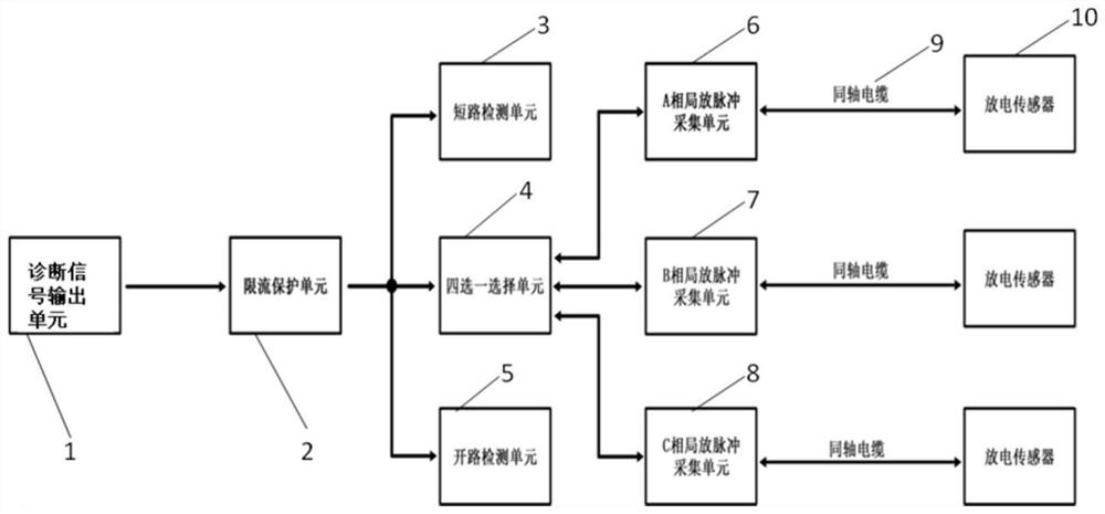
[0049] Such as figure 1 As shown, a partial discharge on-line monitoring device integrated with a fault detection system is shown, including a diagnostic signal output unit 1, a current limiting protection unit 2, a short circuit detection unit 3, a selection unit 4, an open circuit detection unit 5, a phase A Discharge pulse acquisition unit 6, phase B partial discharge pulse acquisition unit 7, phase C partial discharge pulse acquisition unit 8, coaxial cable 9, discharge sensor 10, diagnostic signal output unit 1 is a signal source for self-diagnosis, which can output Pulse signal, DC level signal; diagnostic signal output unit 1 connects current limiting protection unit 2 after outputting self-diagnostic signal source to realize signal protection; current limiting protection unit 2 is connected to four-choice one signal selection unit 4, the selection unit 4 Three of them are merged into A-phase partial discharge pulse acquisition unit 6, B-phase partial discharge pulse ac...

Embodiment 2

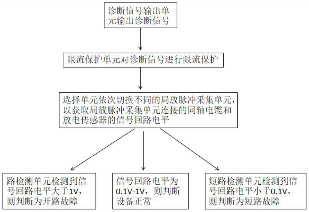
[0065] The diagnostic signal output unit outputs a DC level, such as 5V level, the output current is limited to 10mA through the current limiting protection unit, and the four-selection unit polls and switches A\B\C three-phase acquisition input channel unit, under normal circumstances Because the coaxial cable, discharge sensor and protector make the signal loop level within 1V, the open circuit detection unit can judge according to the level, and it is considered open circuit if it is greater than 1V.

Embodiment 3

[0067] The diagnostic signal output unit outputs a DC level, such as 5V level, the output current is limited to 10mA through the current limiting protection unit, and the four-selection unit polls and switches A\B\C three-phase acquisition input channel unit, under normal circumstances Because the coaxial cable, discharge sensor and protector make the signal loop level above 0.1V, the short circuit detection unit can judge according to the level, and if it is less than 0.1V, it is considered a short circuit.


PUM


Abstract

The invention discloses a fault detection system, and a partial discharge on-line monitoring device and method. The fault detection system comprises a diagnosis signal output unit, a current limiting protection unit, a short circuit detection unit, a selection unit, an open circuit detection unit and a plurality of partial discharge pulse acquisition units, wherein the diagnosis signal output unit is connected with the current limiting protection unit; the current limiting protection unit is connected in parallel with the short circuit detection unit, the selection unit and the open circuit detection unit; the selection unit is connected in parallel with the plurality of partial discharge pulse acquisition units; and the partial discharge pulse acquisition units can be connected with a discharge sensor through coaxial cables. The provided monitoring system capable of identifying a discharge sensor fault and a connection cable fault, and a partial discharge on-line monitoring device and method capable of self-checking.

Description

technical field [0001] The invention relates to the technical field of intelligent manufacturing, in particular to a fault detection system, a partial discharge on-line monitoring device and a method. Background technique [0002] The insulation system of high-voltage equipment will continue to be affected by electrical, heating, mechanical and environmental pressures during operation. Under the action of these factors, the insulation will gradually deteriorate, and eventually cause insulation failure and equipment shutdown, resulting in huge economic losses . To prevent such accidents, the current common practice is to introduce partial discharge on-line monitoring. Through the partial discharge live on-line monitoring device, real-time data on the operation status of high-voltage equipment can be found, and the risk of failure of electrical equipment can be discovered in time. This vital status information helps optimize equipment maintenance strategies, equipment managem...

Claims


Application Information

Patent Timeline
Patent Type & Authority Applications(China)
IPC IPC(8): G01R31/12G01R31/52G01R31/54
CPCG01R31/12G01R31/52G01R31/54
Inventor 沈道义胡勇赵洪义夏善德王龙龙干元锋
Owner 上海格鲁布科技有限公司
Why Eureka
Try Eureka