Supercharge Your Innovation With Domain-Expert AI Agents!

Slip ring encoder and its encoding method

A coding method and encoder technology, applied in the direction of instruments, current collectors, rotary current collectors, etc., can solve the problems of coding with sieve holes, erroneous differential pulse signals, plugging holes, etc.

Active Publication Date: 2017-07-25
NUCTECH CO LTD
View PDF6 Cites 1 Cited by
  • Summary
  • Abstract
  • Description
  • Claims
  • Application Information

AI Technical Summary

Problems solved by technology

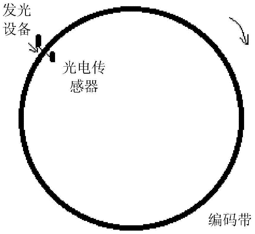
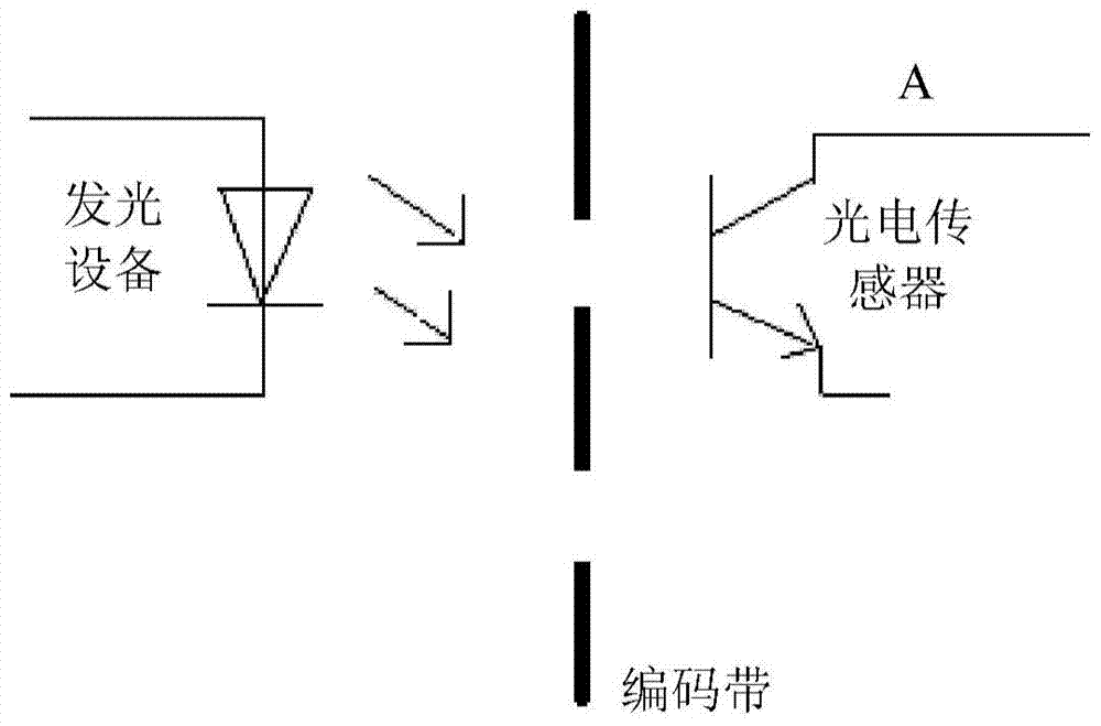
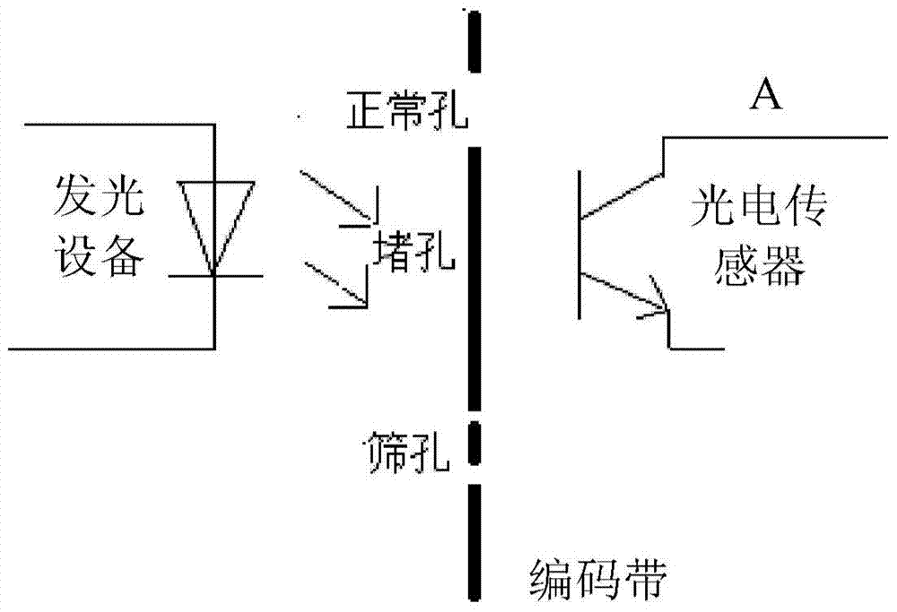
However, when the slip ring encoder is running for a long time, due to the accumulation of dust and other reasons, the code belt part has sieve holes and blocked holes, resulting in the output of wrong differential pulse signals, causing abnormal control or operation of the whole machine

Method used


Image

  • Slip ring encoder and its encoding method
  • Slip ring encoder and its encoding method
  • Slip ring encoder and its encoding method

Examples


Embodiment Construction

[0022] Exemplary embodiments of the present invention will be described in detail below with reference to the accompanying drawings. The following description includes various specific details to assist in understanding, but these should be regarded as exemplary only. Accordingly, those of ordinary skill in the art will recognize that various changes and modifications of the various embodiments described herein can be made without departing from the scope and spirit of the disclosure. Also, descriptions of well-known functions and constructions are omitted for clarity and conciseness.

[0023] The terms and words used in the following description and claims are not limited to their bibliographical meanings, but, but, are merely used by the inventor to carry out a clear and consistent understanding of the invention. Accordingly, it should be apparent to those skilled in the art that the following description of various example embodiments of the present invention are provided ...


PUM


Abstract

Disclosed are a slip ring encoder and an encoding method thereof. The slip ring encoder includes: a code band fixed to the slip ring and having a plurality of holes regularly arranged; at least one pair of first sensors arranged on one side of the code band, each pair The first sensor is configured to generate a first sensing signal and a first redundant sensing signal respectively according to light emitted from the other side of the encoding band and passing through the plurality of holes when the encoding band rotates with the slip ring; at least A signal combining module, connected to the at least one pair of first sensors, is configured to combine the first sensing signal and the first redundant sensing signal to generate a combined sensing signal as a first encoding signal of the slip ring encoder. According to the embodiment of the present invention, redundant sensors are used to provide redundant signals to avoid the influence of foreign objects, improve the stability of encoded signals and ensure the normal operation of the whole machine.

Description

technical field [0001] Exemplary embodiments of the present invention generally relate to the field of encoders, and in particular to a slip ring encoder with redundant sensors and an encoding method thereof. Background technique [0002] Slip rings are commonly used in, for example, CT equipment. Usually, the X-ray source and detector are fixed on the circular slip ring surrounding the object to be inspected. Every time a circle is moved during work, an image of a thickness section of the object to be inspected is obtained. In the existing CT equipment, in order to obtain image information of different viewing angles, the rotation of the slip ring is required, and the position and rotational speed information during the rotation of the slip ring is required. For this reason, a slip ring encoder is designed. Its main function is to convert the information of the position and speed of the slip ring rotation into two orthogonal differential pulse signals of A and B phases and ...

Claims


Application Information

Patent Timeline
Patent Type & Authority Patents(China)
IPC IPC(8): G01D5/36
CPCG01D5/24461G01D5/24476G01D5/3473H01R39/08
Inventor 朱玉民张金宇丁辉唐虎
Owner NUCTECH CO LTD
Features
  • R&D
  • Intellectual Property
  • Life Sciences
  • Materials
  • Tech Scout
  • Unparalleled Data Quality
  • Higher Quality Content
  • 60% Fewer Hallucinations
Learn More