Roller threader

A threading machine and roller-type technology, applied in the direction of optical fiber/cable installation, cable laying equipment, etc., can solve the problems of high labor intensity, worker suffocation, low efficiency, etc., and achieve the effect of high production efficiency and less injury

Active Publication Date: 2015-07-01
海宁市钱塘新农村开发有限公司
View PDF5 Cites 3 Cited by
  • Summary
  • Abstract
  • Description
  • Claims
  • Application Information

AI Technical Summary

Problems solved by technology

[0002] With the increase of buried pipelines in cities, the workload of threading in pipes is increasing, but at present, these are all done manually with the help of threaders (such as fiberglass threaders), which

Method used


Image

  • Roller threader
  • Roller threader

Examples


Embodiment Construction

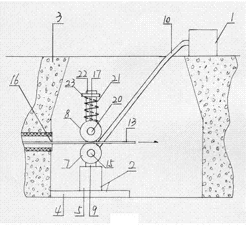
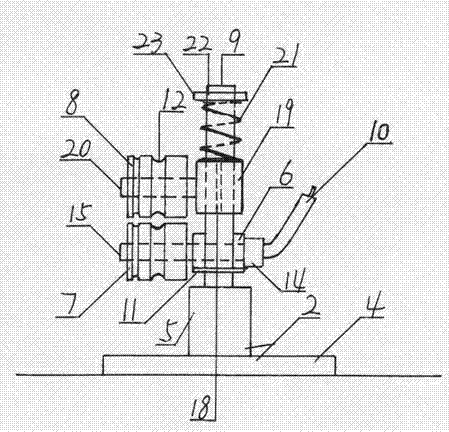
[0016] Such as figure 1 , 2 As shown, a roller-type threading machine is used to pull the optical cable directly by means of the fiberglass rod of the threader or directly to achieve the purpose of mechanized construction. The structure of the machine is composed of a vibrating rod 1 and a threading machine 2; the vibrating rod 1 is used as the power of the threading machine 2; the vibrating rod 1 is driven by an internal combustion engine, and the vibrating rod 1 adopts a plug-in concrete vibrating rod; Set on the trolley on the ground for easy moving;

[0017] The threading machine 2 can be placed in the inspection shaft 3 where the pipeline is laid, so as to facilitate the threading operation; the threading machine 2 is composed of a chassis 4, a hydraulic cylinder 5, a bearing seat 6, a driving wheel 7, and a driven wheel 8; the chassis 4 is a rectangular Corner steel plate; a hydraulic cylinder 5 is provided on the chassis 4; the hydraulic cylinder 5 adopts a manual one...


PUM


Abstract

A roller threader comprises a vibrating rod and a threading unit; the vibrating rod and the threading unit transmit power through a flexible shaft; the threading unit can be accommodated in a manhole; the threading unit is formed by connecting a bottom plate, a hydraulic cylinder, a bearing block, a driving wheel and a driven wheel; the hydraulic cylinder is disposed on the bottom plate; the driving wheel and the driven wheel are mounted on an ejector rod of the hydraulic cylinder; the driving wheel and the driven wheel are externally provided with a plurality of grooves; a sleeve, a spring and an elastic fastener are mounted on the ejector rod; the elastic fastener compresses the spring on a shaft sleeve; the spring elastically drives the driven wheel to attach to the driving wheel.

Description

technical field [0001] A roller threading machine belongs to the field of line tools. Background technique [0002] With the increase of buried pipelines in cities, the workload of threading in pipes is increasing, but at present, these are all done manually with the help of threaders (such as fiberglass threaders), which is not only inefficient but also very labor-intensive, and occasionally There will be reports of suffocation accidents in the inspection shaft of workers, so it is necessary to realize mechanized threading construction. Contents of the invention [0003] The purpose of this application is to provide a roller-type threading machine, which can be used to pull the optical cable directly by means of the fiberglass rod of the threader, so as to realize the purpose of mechanized construction. The structure of the machine is composed of a vibrating rod and a threading machine; the vibrating rod is used as the power of the threading machine; the vibrating rod...

Claims


Application Information

Patent Timeline
IPC IPC(8): H02G1/08G02B6/54
Inventor 冯莉莉
Owner 海宁市钱塘新农村开发有限公司
Why Eureka
Try Eureka