Cell module

A battery module, single cell technology, applied in secondary batteries, battery pack components, battery/battery traction, etc., can solve problems such as water immersion, corrosion, and accumulation of bottom plate components, and achieve the effect of preventing corrosion

Inactive Publication Date: 2015-07-01
MITSUBISHI HEAVY IND LTD
View PDF8 Cites 8 Cited by
  • Summary
  • Abstract
  • Description
  • Claims
  • Application Information

AI Technical Summary

Problems solved by technology

[0008] However, in the above-mentioned battery module, the through-holes are pierced in the up-down direction, so water may infiltrate from below.
In addition, when the battery pack is cooled, dew condensation may occur, and the water generated by the dew condensation may fall, and the water may accumulate on the bottom plate member.
Therefore, adjacent single cells may be electrically connected through water, and problems such as corrosion caused by the electrical connection may occur.

Method used


Image

  • Cell module
  • Cell module
  • Cell module

Examples


Embodiment Construction

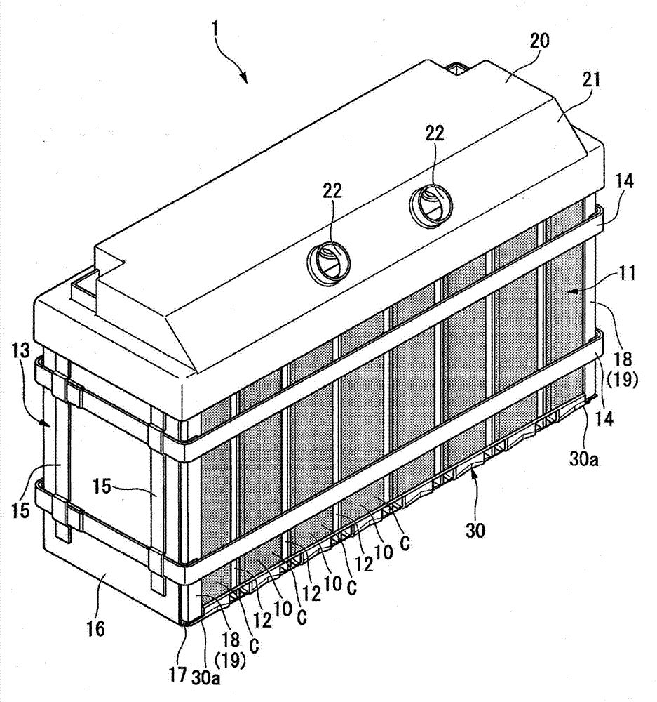
[0029] Next, the battery module 1 according to the first embodiment of the present invention will be described based on the drawings.

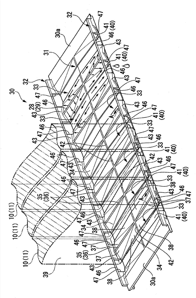
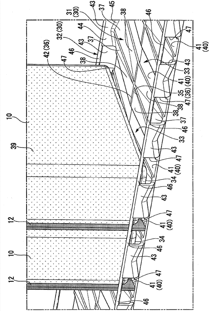
[0030] figure 1 The battery module 1 of this embodiment is shown. Such as figure 1 As shown, the battery module 1 includes a battery pack 11 . The battery pack 11 is formed by arranging a plurality of single cells 10 in a row along the thickness direction thereof. The unit cell 10 is formed in a substantially rectangular parallelepiped shape with electrodes (not shown) on its upper portion. The above-mentioned electrodes of the individual cells 10 are connected in series or in parallel by tie rods (not shown) or the like. The battery pack 11 includes a flat insulating member (insulating plate) 12 between adjacent single cells 10 . These insulating members mainly electrically insulate the opposing wall surfaces of the cases C of the individual cells 10 from each other.

[0031] The battery module 1 includes a case 13 that houses the batte...


PUM


Abstract

In the present invention, provided are battery packs (11) in which a plurality of single cells (10) are arranged, and a support plate (30) for supporting the battery packs (11). The support plate (30) has discharge parts (33) in the direction perpendicular to the direction in which the unit cells (10) are disposed and in the direction of extension of the support plate (30), and that are for discharging a liquid which is on the support plate (30).

Description

technical field [0001] The present invention relates to a battery module including a battery pack in which a plurality of single cells are arranged. [0002] this application claims priority based on Japanese Patent Application No. 2012-255698 for which it applied to Japan on November 21, 2012, and uses the content here. Background technique [0003] Among battery modules including a battery pack in which a plurality of single cells are arranged, a battery module including a bottom plate member that supports the battery pack from below is known. In such a battery module, in order to efficiently cool the battery pack, a technique has been proposed in which a bottom plate member is vertically provided with through holes through which cooling air passes (see, for example, Patent Document 1). [0004] prior art literature [0005] patent documents [0006] Patent Document 1: Japanese Patent Laid-Open No. 2011-096398 [0007] The problem to be solved by the invention [0008...

Claims


Application Information

Patent Timeline
Patent Type & Authority Applications(China)
IPC IPC(8): H01M2/10H01M50/209H01M50/289
CPCH01M10/6563H01M2/1016H01M10/6557H01M10/613H01M10/647H01M50/289H01M50/209B60L2240/545B60L58/26B60L50/64Y02T10/70Y02E60/10B60K1/04
Inventor 智叶大介
Owner MITSUBISHI HEAVY IND LTD
Why Eureka
Try Eureka