Electric Device System

A technology of electrical equipment and electrical connection, applied in the direction of electrical equipment structural parts, electrical components, circuits, etc., can solve the problems of disconnection, error, communication error, etc., and achieve the effect of suppressing electrical connection

Active Publication Date: 2016-07-20
ORMON CORP
View PDF8 Cites 1 Cited by
  • Summary
  • Abstract
  • Description
  • Claims
  • Application Information

AI Technical Summary

Problems solved by technology

[0012] However, in the case of such constitution, when one of a pair of electrical equipment units is assembled on the other, the connection terminal of the one protruding from the outer surface of the electrical equipment unit slides on the outer surface of the other electrical equipment unit. Therefore, when sliding, there is a risk that the connection terminal will bring in foreign matter such as dust adhering to the casing or cutting chips generated by cutting a part of the surface of the casing will be brought in as foreign matter.
In this case, in the state where one of the pair of electrical equipment units has been assembled to the other, the first connection terminal and the second connection terminal are cut off due to the foreign matter entering between the first connection terminal and the second connection terminal. Conduction between connection terminals, which can cause communication errors
[0013] In addition, in the state where one of a pair of electrical equipment units is assembled on the other, if the foreign matter does not enter between the first connection terminal and the second connection terminal, since the foreign matter is located between the first connection terminal and the second connection terminal, In the vicinity of the contact point of the second connection terminal, when an impact is applied to the electrical equipment unit from the outside, the relative position between the first connection terminal and the second connection terminal changes, and there is also a possibility that this foreign matter enters the first connection terminal and the second connection terminal. In the case of connection terminals, in this case, the conduction between the first connection terminal and the second connection terminal will be cut off, which will cause a communication error.

Method used


Image

  • Electric Device System
  • Electric Device System
  • Electric Device System

Examples


Embodiment approach 1

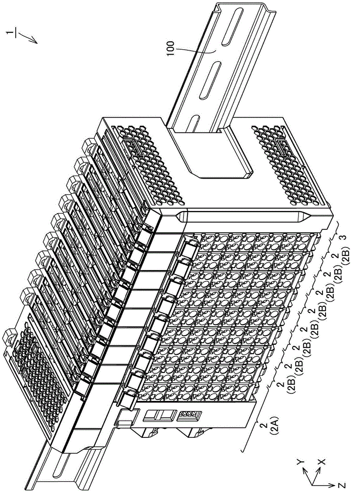
[0079] figure 1 It is a perspective view of an assembled state of the remote terminal device according to Embodiment 1 of the present invention. First, refer to the figure 1 The configuration of the remote terminal device 1 of this embodiment will be described.

[0080] Such as figure 1 As shown, the remote terminal device 1 has a communication unit 2A, a plurality of I / O units 2B, and an end cover 3 . The one communication unit 2A, the plurality of I / O units 2B, and one end cover 3 are assembled in a manner of being arranged along the first direction, that is, the X-axis direction. Among them, the communication unit 2A and the plurality of I / O units 2B correspond to the plurality of electrical equipment units 2 constituting the remote terminal device 1 as an electrical equipment system. In addition, in the present embodiment, all of the plurality of I / O units 2B have the same shape and structure.

[0081] When the remote terminal device 1 is viewed from the front surface...

Embodiment approach 2

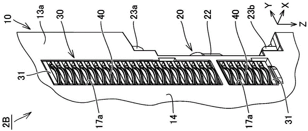
[0153] Figure 10A is a partially cutaway perspective view of a terminal box including a portion of a first connection terminal of an I / O unit in a remote terminal device according to Embodiment 2 of the present invention, Figure 10B It is a partial cutaway perspective view of the terminal box of the part including the 2nd connection terminal of this I / O unit. First, refer to the Figure 10A , 10B The detailed structure of the terminal box 30' included in the I / O unit in the remote terminal device of this embodiment and the first connection terminal 40 and the second connection terminal 50 included in the terminal box 30' will be described.

[0154] Such as Figure 10A as well as Figure 10B As shown, the terminal box 30' of the I / O unit in the remote terminal device of this embodiment has the same structure as that of Embodiment 1 in the structure of the plurality of first connection terminals 40. On the other hand, in the structure of the plurality of first connection t...


PUM


Abstract

Provided is an electric device system (1) that can prevent blocking of electric connection between electric device units (2). The electric device system (1) includes a first unit (2B1) and a second unit (2B2) that are of the electric device units (2) adjacent to each other. An elastically deformable first connecting terminal (40) is provided in the first unit (2B1), and a second connecting terminal (50) is provided in the second unit (2B2). When the first unit (2B1) is assembled in the second unit (2B2), the first connecting terminal (40) comes into contact with the second connecting terminal (50) after sliding on an outer surface (14) of a casing (10) of the second unit (2B2). A bulging surface (41) is provided in an exposed surface of the first connecting terminal (40), and a recess (52) is provided in an exposed surface of the second connecting terminal (50). A part of the bulging surface (41) and a part of an opening edge (52a) of the recess (52) come into press-contact with each other by fitting a part of the bulging surface (41) in the recess (52), thereby establishing electric conduction between the first connecting terminal (40) and the second connecting terminal (50).

Description

technical field [0001] The present invention relates to an electrical equipment system composed of a plurality of electrical equipment units. Background technique [0002] Conventionally, there are various types of electrical equipment systems constituted by a plurality of electrical equipment units. As one of them, there is known an electrical equipment system including a plurality of electrical equipment units arranged in a predetermined direction and electrically connected to each other. As a representative example of the electric equipment system of this structure, the remote terminal apparatus of a programmable logic controller (PLC) (it abbreviates simply as a remote terminal apparatus hereafter) is mentioned. [0003] The remote terminal device includes a communication unit and one or more I / O units (input and output units) capable of communicating with the communication unit via a serial bus and a one-way communication line respectively. The above-mentioned communic...

Claims


Application Information

Patent Timeline
Patent Type & Authority Applications(China)
IPC IPC(8): H01R13/24H01R13/629
CPCH01R13/2492H01R13/629H01R9/2675H01R13/2442H01R13/514H05K7/1474H05K7/1465H05K7/1467
Inventor 三浦嘉良山根顺东义巳岩崎晋也山田大辅户水基之
Owner ORMON CORP
Why Eureka
Try Eureka