A kind of swirl type drainage concentrator for building kitchen
A swirl type and collector technology, which is applied to the field of drainage collectors for building kitchens, can solve the problems of easy drying of floor leaks, easy blockage of pipes, and difficult maintenance, etc., and achieves the effect of improving drainage capacity and improving cleanliness.
- Summary
- Abstract
- Description
- Claims
- Application Information
AI Technical Summary
Problems solved by technology
Method used
Image
Examples
Embodiment 1
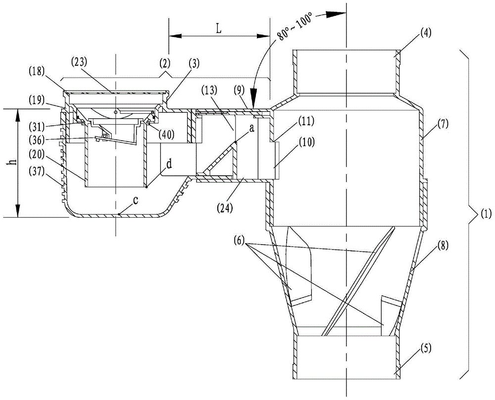
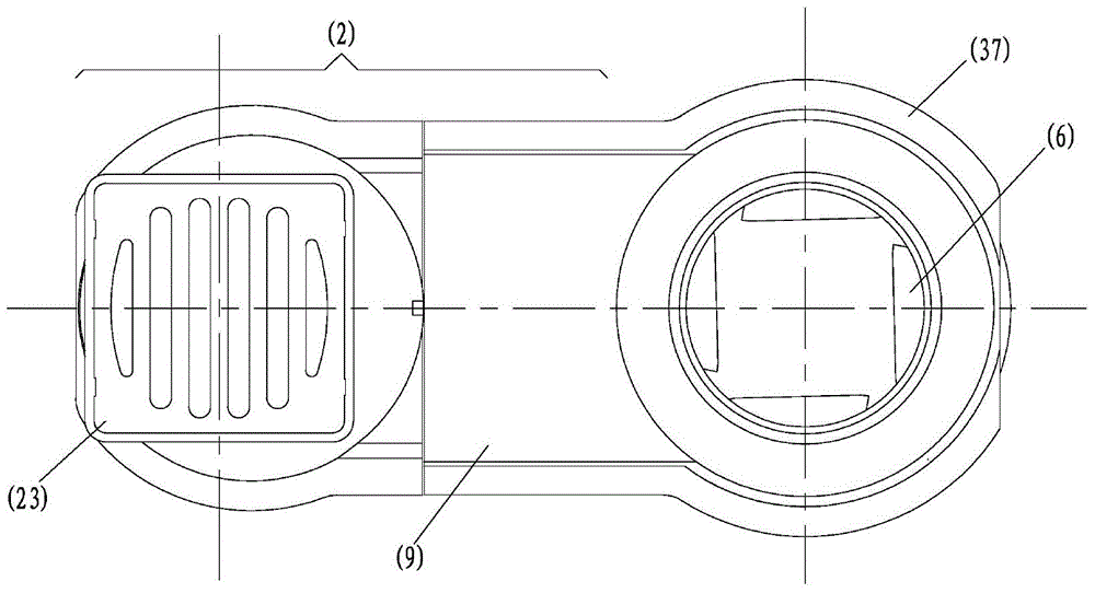
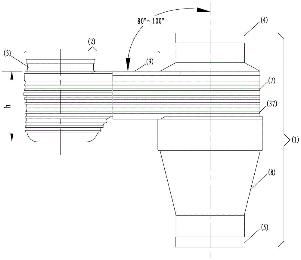
[0029] Such as figure 1 , 2 As shown in , 3 and 4, the swirling flow drainage concentrator for building kitchens according to the present invention is composed of a standpipe drainage section 1, a horizontal pipe drainage collection section 2 and a water seal member 3. The riser drainage section 1 is connected up and down, the middle section has expansion, and there are guide vanes 6 in the expansion section. The expansion section is divided into straight section expansion 7 and funnel-shaped expansion 8. There is a length of 110mm in the expansion section of straight section 7. The pipe section with the same outer diameter, the straight section expansion 7 is located at the upper end of the funnel-shaped expansion 8, below the upper interface 4, and the funnel-shaped expansion 8 is above the lower interface 5; Connected with the hollow of the riser drainage section 1, the horizontal surface 9 of the horizontal pipe drainage collection section 2 and the lower inner wall are p...
Embodiment 2
[0031] Such as Figure 5 As shown, the lower part 20 of the water-sealed body member of the swirl-type drainage collector for building kitchens according to the present invention and the middle part 19 of the water-sealed body member are not integral components, and the inner diameter of the middle part 19 of the water-sealed body is larger than that of the water-sealed body. The external diameter of member lower part 20 lower end is less than the outer diameter of water seal member lower part 20 upper end 33, and there is groove 34 on the outer diameter of water seal member lower part 20 upper end 33, and rubber ring 35 is arranged in groove 34, rubber ring 35 Located in the inner wall of the middle part 19 of the water seal member; when it is necessary to overhaul and clean the horizontal pipe drainage collection section 2, it is only necessary to pull out the lower part 20 of the water seal member from the middle part 19 of the water seal member, (the water seal member Ther...
Embodiment 3
[0033] Such as Figure 5 , 6As shown, the water seal component lower part 20 and the water seal component middle part 19 of the building kitchen cyclone drainage concentrator according to the present invention are not integral components, and the inner diameter of the water seal component middle part 19 lower end 31 is 70 mm, and the water seal component The external diameter of member lower part 20 lower end is 68mm, and the external diameter of water sealing member lower part 20 upper end 33 is 86mm, and the lower surface of water sealing member middle part 19 lower end 31 contacts with the lower surface of water sealing member lower part 20 upper end 33, and all It is a plane, there are two grooves 39 on the lower end 31 of the middle part 19 of the water seal member, the diameter of the groove is 76 mm, and the arc length is 10 mm. The outer diameter is 75 mm, the arc length is 9 mm, the upper and lower thickness of the lower end 31 of the middle part of the water seal me...
PUM
 Abstract
Description
Claims
Application Information
 - R&D
- Intellectual Property
- Life Sciences
- Materials
- Tech Scout
- Unparalleled Data Quality
- Higher Quality Content
- 60% Fewer Hallucinations
Browse by: Latest US Patents, China's latest patents, Technical Efficacy Thesaurus, Application Domain, Technology Topic, Popular Technical Reports.
© 2025 PatSnap. All rights reserved.Legal|Privacy policy|Modern Slavery Act Transparency Statement|Sitemap|About US| Contact US: help@patsnap.com


