
Hot channel afterburning combustion chamber

A combustion chamber and hot channel technology, which is applied in combustion chambers, continuous combustion chambers, combustion methods, etc., can solve the problems of severe cooling of turbine first-stage stator blades, reduced heat energy of turbine first-stage moving blades, and difficulty in maintaining service life, etc. Achieve the effect of improving efficiency and working ability, improving service life and reducing front temperature

Inactive Publication Date: 2015-07-15
CHINA UNITED GAS TURBINE TECH CO LTD
View PDF5 Cites 0 Cited by
  • Summary
  • Abstract
  • Description
  • Claims
  • Application Information

AI Technical Summary

Problems solved by technology

Usually, due to factors such as expansion work and cold air injection in the airflow channel of the first stage turbine vane, the temperature of the gas will drop by 80-100 degrees Celsius, resulting in a decrease in the heat energy driving the turbine first stage rotor blade and a decrease in the work ability
In the prior art, in order to improve the working ability of the gas turbine, the temperature before the turbine has been increasing, resulting in a very serious cooling problem of the first-stage stator blade of the turbine, and it is difficult to maintain a long service life

Method used


Image

  • Hot channel afterburning combustion chamber
  • Hot channel afterburning combustion chamber
  • Hot channel afterburning combustion chamber

Examples


Embodiment 1

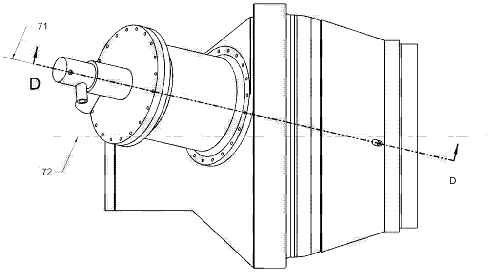
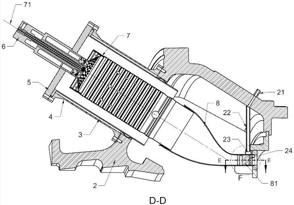
[0031] Such as Figure 1-4 As shown, the hot passage post-combustion combustion chamber of this embodiment includes: a fuel pressure cylinder 2, a casing 4 connected to the fuel pressure cylinder 2 at the rear end, an end cover 5 connected to the front end of the casing 4, and an end cover 5 connected to the end cover 5. The nozzle 6 connected to the inside of the casing 4 is connected to the guide bush 3 , the flame tube 7 located inside the guide bush 3 and the front end is connected to the nozzle 6 , and the transition section 8 whose inlet is connected to the rear end of the flame tube 7 .

[0032] The included angles between the central axis 71 of the combustion chamber and the central axis 72 of the gas turbine in the axial direction and the circumferential direction of the hot passage post-firing combustor are both greater than 0°. Preferably, the included angle between the combustion chamber central axis 71 of the hot passage post-firing combustor and the gas turbine c...

Embodiment 2

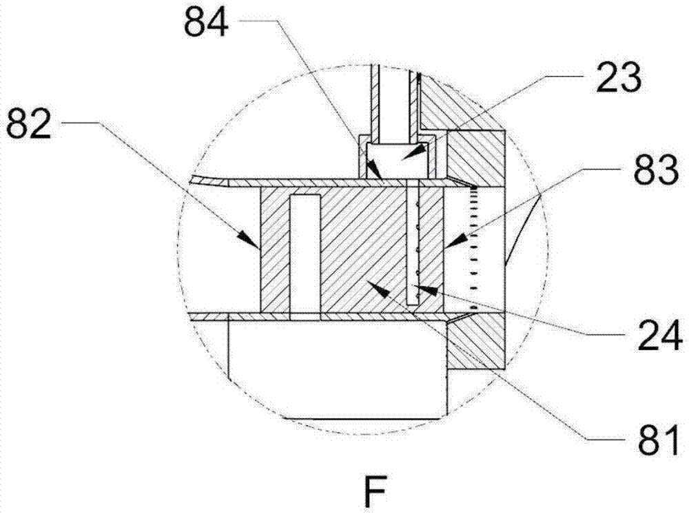
[0039] Such as Figure 5-7 As shown, the difference between the hot passage post-firing combustor of this embodiment and the embodiment is that a fuel injection device is provided downstream of the outlet guide vane. The specific structure of the fuel injection device is as follows: the outlet guide vane 81 is an airfoil shape, the inside of the outlet guide vane 81 is provided with a cooling device, the downstream of the outlet guide vane is provided with at least one fuel injection pipe 24, and the fuel injection pipe 24 is provided with There are fuel injection holes 25 for injecting fuel towards the rear of the outlet guide vanes. The fuel pressure cylinder 2 is provided with at least one fuel main pipe 21, and the transition section 8 is provided with an outer ring fuel pipe 23 outside the fuel injection pipe 24, and a main fuel pipe 22 is arranged between the fuel main pipe 21 and the outer ring fuel pipe 23. The main pipe 21 , the main fuel pipe 22 , the outer ring fue...


PUM

PropertyMeasurementUnit
Angleaaaaaaaaaa

Abstract

The invention relates to the technical field of combustion gas turbines, in particular to a hot channel afterburning combustion chamber. The hot channel afterburning combustion chamber comprises a combustion pressure cylinder, a machine case, an end cover, a nozzle, a flow guiding bushing, a flame tube and a transition section, wherein the rear end of the machine case is connected with the combustion pressure cylinder; the end cover is connected with the front end of the machine case; the nozzle is connected with the end cover; the flow guiding bushing is connected at the inner side of the machine case; the flame tube is positioned in the flow guiding bushing; the front end of the flame tube is connected with the nozzle; the inlet of the transition section is connected with the rear end of the flame tube; the outlet of the transition section is provided with an outlet guide vane; the rear end or the downstream part of the outlet guide vane is provided with a fuel injection device. According to the hot channel afterburning combustion chamber, the fuel injection device is arranged at the rear side of the outlet guide vane, and less fuel is injected into a turbine first-level movable vane so as to compensate the airflow temperature drop in an outlet guide vane channel, so that the temperature of airflow which enters into the turbine first-level movable vane is increased, and the efficiency and power applying capability of the combustion gas turbine can be effectively improved; under the condition of guaranteeing the total efficiency of the combustion gas turbine to be constant, the temperature in front of the outlet guide vane can be reduced, the difficulties for designing the outlet guide vane and a turbine are lowered, and the service life of the whole gas turbine is prolonged.

Description

technical field [0001] The invention relates to the technical field of gas turbines, in particular to a post-combustion combustion chamber of a gas turbine hot channel. Background technique [0002] The basic working process of a gas turbine is that the air entering the gas turbine is compressed by the compressor; it is mixed with fuel in the combustion chamber for combustion; the high-temperature and high-pressure gas at the exit of the combustion chamber enters the turbine to drive the turbine to do work, and the temperature and pressure of the gas are within the range of the turbine. The gap between the stationary blades and moving blades of each stage is lowered step by step, converting part of the thermal energy of the gas into mechanical energy, which drives the compressor to rotate, and the other part of the thermal energy is converted into mechanical energy, which is used for power or power generation. [0003] Under the condition of a certain gas turbine flow rate, ...

Claims


Application Information

Patent Timeline
IPC IPC(8): F23R3/34
Inventor 吕煊方子文李珊珊郭庆波
Owner CHINA UNITED GAS TURBINE TECH CO LTD
Learn More