Temperature control method and device for diesel particulate filter (DPF) during regeneration

A temperature control method and DPF technology, which is applied to the electronic control of mufflers, exhaust devices, exhaust treatment devices, etc., can solve the problems of DPF burnout and the inability to guarantee the absolute safety of DPF temperature, so as to reduce the temperature before and ensure the temperature Absolutely safe, prevent burning effect

Active Publication Date: 2020-09-18
WEICHAI POWER CO LTD
View PDF6 Cites 0 Cited by
  • Summary
  • Abstract
  • Description
  • Claims
  • Application Information

AI Technical Summary

Problems solved by technology

[0003] However, DPF regeneration technology is still a difficult problem for particulate matter regeneration. Therefore, engine manufacturers, catalyst manufacturers and some universities must use a large number of diesel engine bench experiments to explore the particulate matter regeneration performance in DPF.
The current strategy is based on the maximum oil quantity limit of the exhaust temperature before the DPF. When the temperature before the DPF meets the requirements, the problem of DPF burning will still occur if the temperature upstream of the SCR exceeds the limit, and the temperature during DPF regeneration cannot be guaranteed to be absolutely safe.

Method used


Image

  • Temperature control method and device for diesel particulate filter (DPF) during regeneration
  • Temperature control method and device for diesel particulate filter (DPF) during regeneration
  • Temperature control method and device for diesel particulate filter (DPF) during regeneration

Examples


Embodiment Construction

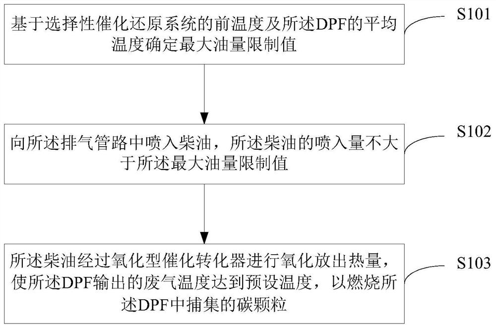
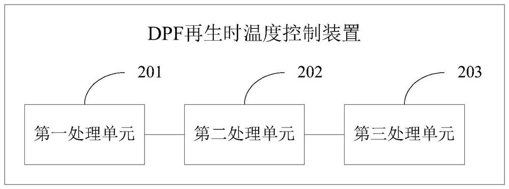
[0033] This application provides a temperature control method and device during DPF regeneration, which is used to prevent the particulate matter filter DPF from being burned due to excessive temperature during regeneration, by increasing the maximum oil quantity limit based on the front temperature of the selective catalytic reduction system and the average temperature of the DPF Function, the limited oil quantity before the DPF and the limited oil quantity before the selective catalytic reduction system take the smaller one as the final limited oil quantity, and quickly reduce the front temperature of the selective catalytic reduction system by reducing the limited oil quantity of the HC injection quantity to prevent DPF burned.

[0034] The purpose of the invention of the present application is: how to avoid the problem of DPF burning and ensure the absolute safety of the temperature during DPF regeneration.

[0035] The following will clearly and completely describe the te...


PUM


Abstract

The invention provides a temperature control method and device for a diesel particulate filter (DPF) during regeneration. The temperature control method and the temperature control device for the DPFduring regeneration are used for preventing the DPF from being burned down during regeneration due to excess temperature. The temperature control method for the DPF during regeneration comprises the steps of firstly determining a maximum oil mass limit value based on the front temperature of a selective catalytic reduction system and the average temperature of the DPF; then injecting diesel fuel into a gas exhaust pipeline, wherein the injecting amount of the diesel fuel is not larger than the maximum oil mass limit value; and finally, carrying out oxidization on the diesel fuel through an oxidizing catalytic converter so as to release heat, so that the temperature of exhaust gas output by the DPF reaches to the preset temperature, and carbon particulates captured in the DPF are burned. According to the temperature control method and the temperature control device for the DPF during regeneration provided by the invention, through increasing the maximum oil mass limit value based on thefront temperature of the selective catalytic reduction system and the average temperature of the DPF, the injecting amount of the diesel fuel injected into the gas exhaust pipeline is controlled andreduced, and the front temperature of the selective catalytic reduction system is quickly reduced, so that the DPF is prevented from being burned down, and the temperature of the DPF during regeneration is ensured to be safe absolutely.

Description

technical field [0001] The application belongs to the technical field of diesel engine temperature control, and in particular relates to a temperature control method and device during DPF regeneration. Background technique [0002] Diesel engines are widely used due to their fuel economy and high reliability, but their particulate matter (PM) emissions are large, which are 30 to 80 times that of gasoline engines of the same power. With the development of technology, diesel particulate filter (DPF) has become one of the most effective devices for reducing PM outside the machine; with the increasingly stringent national VI emission standards, DPF has become an essential choice for diesel engine aftertreatment systems. [0003] However, DPF regeneration technology is still a difficult problem in particulate matter regeneration. Therefore, engine manufacturers, catalyst manufacturers and some universities must conduct a large number of diesel engine bench experiments to explore ...

Claims


Application Information

Patent Timeline
IPC IPC(8): F01N3/025F01N9/00F01N13/00
CPCF01N3/0253F01N9/002F01N13/009F01N2250/02Y02T10/40
Inventor 解家报高红臣甄雷赵甲运
Owner WEICHAI POWER CO LTD
Why Eureka
Try Eureka