Eureka AIR delivers breakthrough ideas for toughest innovation challenges, trusted by R&D personnel around the world.

Switching device group and linkage mechanism thereof

A technology of switching device and linkage mechanism, which is applied to electrical components, electrical switches, circuits, etc., can solve the problems of the front wall drive shaft 84 bearing large torque, damage to the drive shaft, and the influence of synchronization effects.

Active Publication Date: 2015-07-15
SIEMENS AG
View PDF5 Cites 0 Cited by
  • Summary
  • Abstract
  • Description
  • Claims
  • Application Information

AI Technical Summary

Problems solved by technology

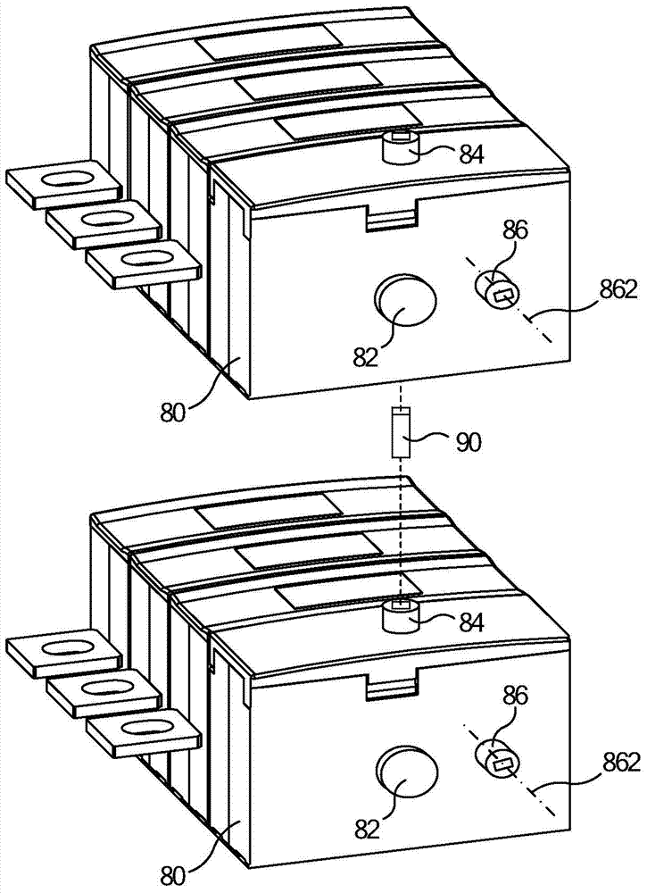
[0004] After adopting the above method, because there is inevitably a gap between the connecting piece 90 and the front wall drive shaft 84, and when the switching device passes through the dead point position, the front wall drive shaft 84 bears a large moment, and the synchronization effect may be affected. influences
In addition, since the drive shafts of each switching device are generally designed to withstand the torque generated by only one switching device, the drive shaft may be damaged in the above connection mode.

Method used


Image

  • Switching device group and linkage mechanism thereof
  • Switching device group and linkage mechanism thereof
  • Switching device group and linkage mechanism thereof

Examples


Embodiment Construction

[0039] In order to have a clearer understanding of the technical features, purposes and effects of the invention, the specific embodiments of the present invention are now described with reference to the accompanying drawings, in which the same reference numerals represent components with the same or similar structures but the same functions.

[0040] In this article, "schematic" means "serving as an example, example or illustration", and any illustration or implementation described as "schematic" should not be interpreted as a more preferred or more advantageous Technical solutions.

[0041] In order to make the drawing concise, each drawing only schematically shows the parts related to the present invention, and they do not represent the actual structure of the product. In addition, in order to make the drawings concise and easy to understand, in some drawings, only one of the components having the same structure or function is schematically shown, or only one of them is mar...


PUM


Abstract

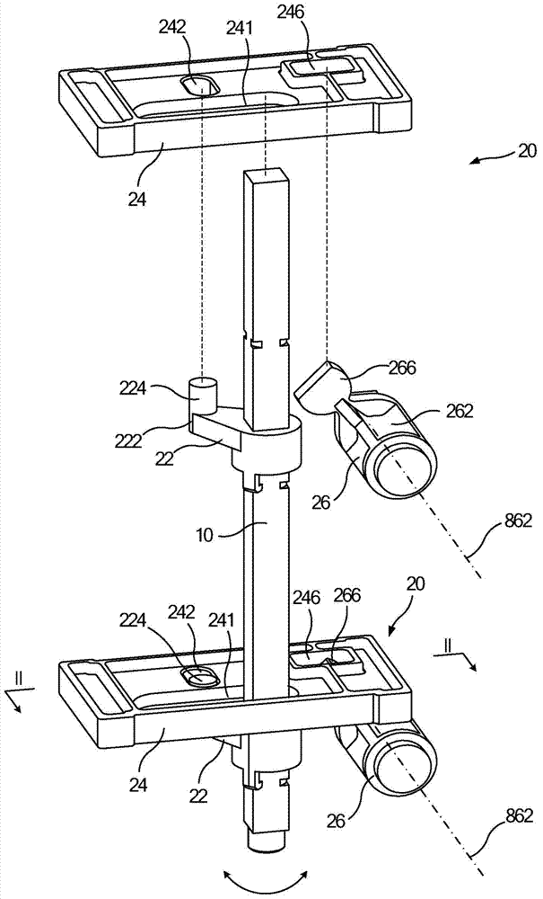
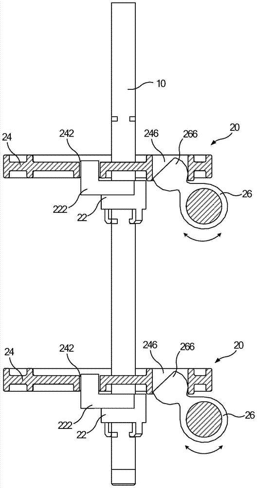
The invention discloses a linkage mechanism of a switching device group. The linkage mechanism comprises a rotatable linkage rod (10) and a plurality of linkage components (20), wherein each linkage component comprises a swing piece (22), a sliding piece (24) and an execution piece (26); the swing pieces can be fixed with the linkage rod, and are provided with swing ends (222) capable of rotating along with the linkage rod; the sliding pieces are provided with first contact parts (242) and second contact parts (246); the first contact parts are contacted with the swing ends; the execution pieces can be fixed with a driving shaft of a switching device, and are provided with execution ends (266) capable of rotating along with the driving shaft; the execution ends are contacted with the second contact parts; the rotatable swing ends can push the sliding pieces to move in a linear direction by the first contact parts; and the second contact parts of the sliding pieces can push the driving shaft to rotate between an off position and an on position by the execution ends. The linkage mechanism can realize synchronous operation of multiple switching devices, is good in synchronous effect, and can avoid damage of the driving shaft.

Description

technical field [0001] The present invention relates to a linkage mechanism, in particular to a linkage mechanism of a switching device group, and also relates to a switching device group having the above linkage mechanism. Background technique [0002] In the switching device, by operating the drive shaft to switch between the open position and the closed position, the drive shaft is driven to make the movable contact and the fixed contact contact and separate, thereby realizing the on-off control of the power supply line. Such as figure 1 As shown, the driving shaft of the switching device can generally be designed as a front wall driving shaft 84 perpendicular to the axial direction of the transmission shaft 82 or a side wall driving shaft 86 parallel to the axial direction of the transmission shaft 82 . [0003] When it is necessary to realize the synchronous operation of two or more switching devices, taking two switching devices as an example, due to the restrictions ...

Claims


Application Information

Patent Timeline
Patent Type & Authority Applications(China)
IPC IPC(8): H01H9/26
CPCH01H9/26
Inventor 宋建康何俊杰刘云李翔刘明华
Owner SIEMENS AG
Why Eureka
Eureka Blog
Learn More