Sanding device for wood plastic plate

A wood-plastic board and sanding technology, which is applied in the direction of abrasive belt grinders, grinding/polishing equipment, grinding machines, etc., can solve the problem of inability to accurately ensure that it can be moved back to the second chute, shorten the service life of the sanding belt, and is difficult to restore to Initial position and other issues, to achieve the effect of simple mobile operation

Inactive Publication Date: 2021-02-19
卓雪娇
View PDF5 Cites 0 Cited by
  • Summary
  • Abstract
  • Description
  • Claims
  • Application Information

AI Technical Summary

Problems solved by technology

[0005] 1. Use the elasticity of the spring to make the roller press against the sanding belt. Although it can make the sanding more fully, it also makes the sanding belt always in a tensioned state, which shortens the service life of the sanding belt to a certain extent.
[0006] 2. After the lower end of the connector enters the first chute, it is not easy to return to its original position. It can move down directly along the first chute, and it cannot be accurately ensured that it will move back into the second chute.

Method used


Image

  • Sanding device for wood plastic plate
  • Sanding device for wood plastic plate
  • Sanding device for wood plastic plate

Examples


Embodiment 1

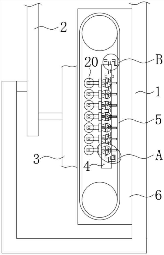
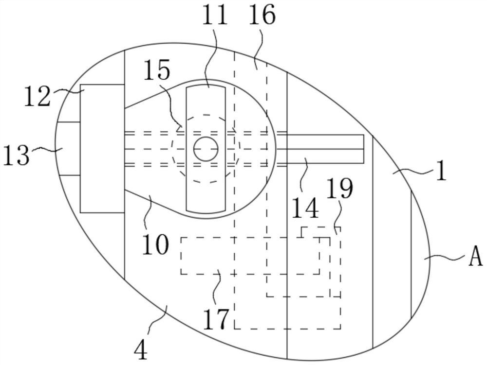
[0029] refer to Figure 1-5 , a wood-plastic board sanding device, including a frame body 1, a connecting plate 2, a wood-plastic board 3, a support beam 4, a sanding belt 5, a board body 6, a groove 7, a groove 2 8, a groove 3 9, support Be provided with a plurality of installation slots-10 on the beam 4, all in each installation slot-10, be installed with a magnetic bar 11 by rotating shaft rotation, on the sanding belt 5, be equipped with a plurality of matching with the magnetic bar 11 by supporting structure. Magnetic block one 12, each magnetic block one 12 is fixedly installed with a mounting rod 13, and a top roller 20 is installed in rotation between the corresponding two mounting rods 13;

[0030] The above points worth noting are as follows:

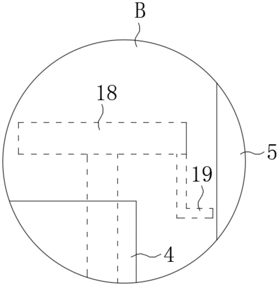
[0031] 1. The support structure is composed of a limit strut 14 and a square hole. A limit strut 14 is fixedly installed on the side of each magnetic block 12 away from the installation rod 13, and the end face shape of the l...

Embodiment 2

[0042] refer to Figure 4 , Figure 6, the difference between this embodiment and the first embodiment is that: a gear two 25 is installed on the rotating shaft through a one-way bearing two 24, and the self-locking direction of the one-way bearing two 24 is opposite to that of the one-way bearing one. There are chute 26, groove body one and groove body two, and groove body one communicates with chute 26 and installation groove two 21, and gear two 25 is located in the groove body, and groove body two communicates with chute 26, and chute 26 Two tooth bars 27 are slidingly installed in the interior, and a back-moving spring (not shown in the figure) is fixedly installed between the bottom wall of the chute 26 and the lower end of the tooth bar two 27, and the tooth bar two 27 is meshed with the gear two 25, A push block 28 is slidably installed in the tank body 2, and a through hole is opened in the middle part of the push block 28, a magnetic block 2 29 and a gear 3 30 are i...


PUM


Abstract

The invention discloses a sanding device for a wood plastic plate. The sanding device comprises a frame body, a connecting plate, a wood plastic plate, a support beam, a sanding belt, a plate body, afirst slot, a second slot and a third slot, wherein a plurality of mounting slots are formed in the support beam; a magnetic rod is rotatably mounted in each of the mounting slots through a rotary shaft; a plurality of first magnetic blocks matched with the magnetic rods are mounted on the sanding belt through a supporting structure; a mounting rod is fixedly mounted on each of the first magneticblocks; and an ejection roller is rotatably mounted between the two corresponding mounting rods. The sanding device disclosed by the invention has the advantages that under cooperation of the magneticrods and the first magnetic blocks, propping action force is applied to the sanding belt when the ejection rollers are sanded, and the propping effect cannot be produced in no need of using; a movingoperation of the ejection rollers is simple, and syncrhonous operation of the plurality of ejection rollers can be realized through a first moving toothed bar; and meanwhile, through arrangement of apush block which can do reciprocating motion, thrust force can be applied to the lower end of a connecting piece, and thus, the situation that the lower end of the connecting piece is moved again into the first slot is ensured.

Description

technical field [0001] The invention relates to the technical field of wood-plastic boards, in particular to a sanding device for wood-plastic boards. Background technique [0002] During the manufacturing and processing of traditional wood-plastic panels, sanding is carried out by sanding machines, and then the burrs are artificially deburred after sanding, and the wood-plastic panels need to be artificially placed horizontally during sanding, which is cumbersome and time-consuming. strenuous. [0003] The Chinese authorized invention patent document with the patent number CN107186587B discloses a wood-plastic panel sanding device, which includes a frame with a sanding structure, a drive mechanism and a connecting piece, and a connecting plate connected to the frame. A side of the connecting plate away from the frame is provided with a first chute, a second chute and a chute, and the first chute and the second chute are parallel. [0004] Although the sanding device solve...

Claims


Application Information

Patent Timeline
Patent Type & Authority Applications(China)
IPC IPC(8): B24B21/12B24B21/14B24B21/18
CPCB24B21/12B24B21/14B24B21/18
Inventor 卓雪娇
Owner 卓雪娇
Why Eureka
Try Eureka