
Visual inspection method and system for assembly line

A visual inspection and assembly line technology, applied in the field of visual systems, can solve problems such as high cost, unfavorable large-scale promotion, and no solution proposed, and achieve the effect of expanding the shooting area

Active Publication Date: 2018-08-28
BEIJING XINGHE TAISHITE TECH
View PDF6 Cites 2 Cited by
  • Summary
  • Abstract
  • Description
  • Claims
  • Application Information

AI Technical Summary

Problems solved by technology

However, in the prior art, since the products (objects) on the conveyor belt are moving, the camera for taking pictures of the objects is fixed. Therefore, there is no simple motion control mechanism to realize the detection of moving objects. Accurately capture the entire area of ​​the
[0003] Moreover, although the prior art involves a device that adopts electrical motion control equipment to take pictures of moving objects, the cost of this detection device is relatively high, which is not conducive to large-scale promotion.
[0004] Aiming at the above problems in related technologies, no effective solution has been proposed yet

Method used

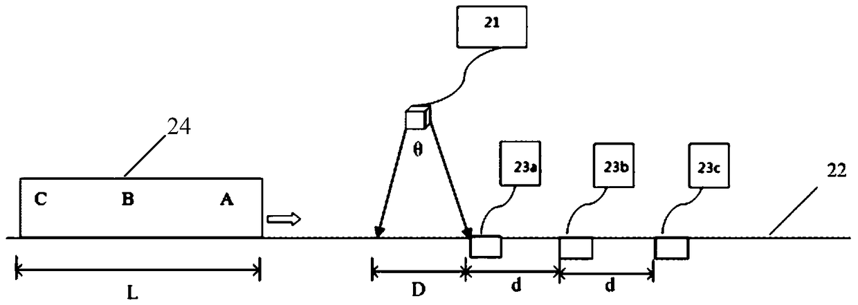
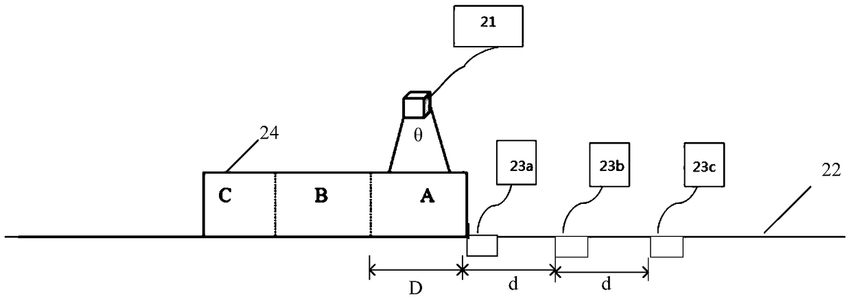

Image

  • Visual inspection method and system for assembly line
  • Visual inspection method and system for assembly line
  • Visual inspection method and system for assembly line

Examples


Embodiment Construction

[0031] The following will clearly and completely describe the technical solutions in the embodiments of the present invention with reference to the accompanying drawings in the embodiments of the present invention. Obviously, the described embodiments are only some, not all, embodiments of the present invention. All other embodiments obtained by persons of ordinary skill in the art based on the embodiments of the present invention belong to the protection scope of the present invention.

[0032] According to an embodiment of the present invention, a visual inspection method for an assembly line is provided.

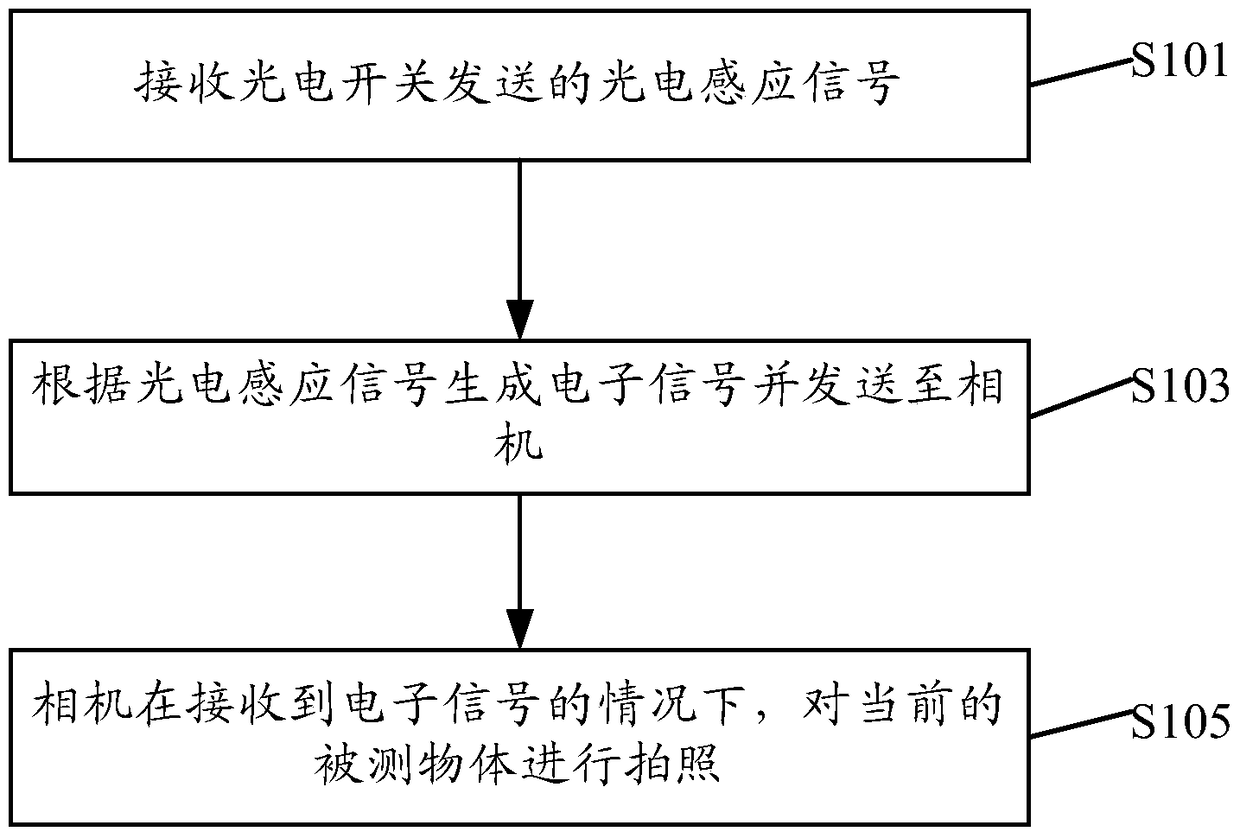
[0033] Such as figure 1 As shown, the visual inspection method according to the embodiment of the present invention includes:

[0034] Step S101, receiving the photoelectric induction signal sent by the photoelectric switch;

[0035] Step S103, generating an electronic signal according to the photoelectric induction signal and sending it to the camera;

[0036] In step...


PUM


Abstract

The invention discloses a visual inspection method and system for assembly lines. The method includes: receiving a photoelectric induction signal sent by a photoelectric switch; generating an electronic signal according to the photoelectric induction signal and sending the electronic signal to a camera; under the condition of receiving the electronic signal, the camera shooting a current inspected object. By receiving the photoelectric induction signal sent by the photoelectric switch and generating the electronic signal to control the inside of a case of the camera, the shooting area of the camera is enlarged, visual inspection efficiency of the object is increased, and meanwhile inspection cost is lowered.

Description

technical field [0001] The present invention relates to a visual system, in particular to a visual inspection method and system for an assembly line. Background technique [0002] In the assembly line of products, in order to ensure the quality of the products produced, it is generally necessary to have a visual inspection device to take pictures of the products produced. However, in the prior art, since the products (objects) on the conveyor belt are moving, the camera for taking pictures of the objects is fixed. Therefore, there is no simple motion control mechanism to realize the detection of moving objects. Accurately capture the entire area. [0003] Moreover, although the prior art involves a device that adopts electrical motion control equipment to take pictures and detect moving objects, the cost of this detection device is relatively high, which is not conducive to large-scale promotion. [0004] For the above-mentioned problems in related technologies, no effecti...

Claims


Application Information

Patent Timeline
Patent Type & Authority Patents(China)
IPC IPC(8): H04N5/232G01D21/00
Inventor 江俭王珏
Owner BEIJING XINGHE TAISHITE TECH
Learn More