Head rest

A technology of a headrest and a clamped part is applied in the field of headrests, which can solve the problems of inability to adjust the position of the front part, and achieve the effect of improving comfort.

Active Publication Date: 2015-07-22
TS TECH CO LTD
View PDF13 Cites 7 Cited by
  • Summary
  • Abstract
  • Description
  • Claims
  • Application Information

AI Technical Summary

Problems solved by technology

However, the headrest described in Patent Document 1 has a structure in which the front portion moves only when the rear end is hit, and the position adjustment of the front portion (hereinafter referred to as the movable side member) in the front-rear direction cannot be performed normally.

Method used


Image

  • Head rest
  • Head rest
  • Head rest

Examples


Deformed example 1

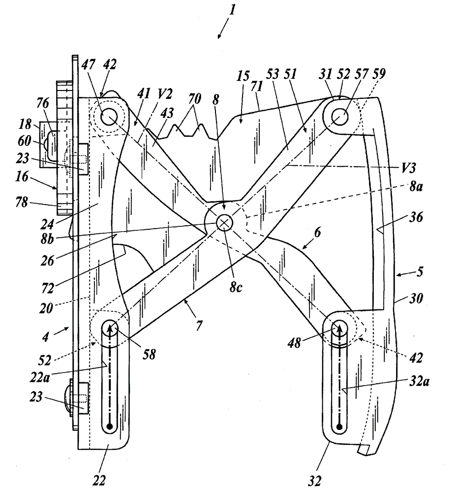
[0264] The engaged portion 15 is formed integrally with the outer link 7 as described above, but although it is not shown, it may be integrally formed with the inner link 6.

[0265] When the engaged portion 15 and the inner link 6 are integrally formed in this way, for example, the engaged portion 15 is provided so as to protrude rearward from the rear surface of the inner link 6. In addition, the curvatures of the arcs of the upper surface portion 71 and the lower surface portion 72 of the engaged portion 15 are changed, and in response to this, the arrangement of the plurality of teeth 70 is also changed. That is, for example, the plurality of teeth 70 are provided on the upper surface portion 71 set to a more gentle curvature.

[0266] Moreover, even in the case where the engaged portion 15 is integrally formed with the inner link 6, as in the case where the outer link 7 is integrally formed, the inner link 6 can rotate the inner link 6. The engaging portion 15 operates. That...

Deformed example 2

[0269] The engaged portion 15 is arranged at the center between the first and second headrest pillars 2a, 2b as described above, but although not shown, it may be opposite to the first and second headrest pillars 2a, 2b. The center of the room is arranged on the left or right.

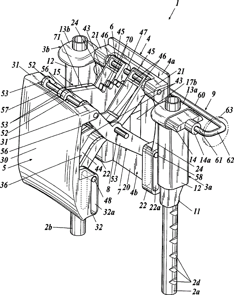
[0270] In the case where the engaged portion 15 is arranged to one side, for example, the engaged portion 15 is provided from the rear surface of the first arm 40 or the second arm 41 constituting the inner link 6 The rear surface protrudes toward the rear.

[0271] In addition, since the engaged portion 15 is arranged on the left or right side with respect to the central portion between the first and second headrest pillars 2a, 2b, the engaged portion 15 can be moved toward the central portion. Staggered on one side. Accordingly, the width dimension of the X-shaped link mechanism can be enlarged in accordance with the amount by which the engaged portion 15 is biased to one side.

[0272] Therefore, the de...

Deformed example 3

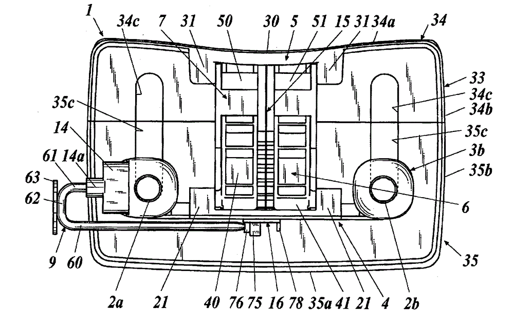
[0274] The engaged portion 15 is arranged at the center between the first and second headrest pillars 2a and 2b as described above, but it may be Picture 12 , Figure 13 As shown, a plurality of them are arranged on the left and right sides with respect to the central portion between the first and second headrest pillars 2a and 2b. In addition, a plurality of engaged portions arranged on the left and right sides are hereinafter referred to as engaged portions 15A and 15A.

[0275] In addition, when there are multiple engaged portions in this way, the inner link 6 does not need to pass the engaged portion 15 in the center, so the first arm 40 and the second arm may not be used. 41's structure. That is, in this modified example, a wide inner link 6A is configured, and the inner link 6A is set to be close to the first arm 40, the second arm 41, and the gap between the arms 40 and 41. The width dimension is approximately equal to the width dimension.

[0276] Furthermore, the outer ...


PUM


Abstract

The purpose of the present invention is to provide a head rest in which the position of a movable member can be adjusted in stages forwards and backwards during normal operation. This head rest (1) is provided with a first and second head rest pillar (2a, 2b), a fixed member (4) provided between the first and second head rest pillars (2a, 2b), a movable member (5) which can move in the direction forwards away from or backwards returning towards the fixed member (4), an X-link mechanism which links the fixed member (4) and the movable member (5) and which has an inside link (6) and an outside link (7) rotatably connected through a cross connection unit (8) in the center, and a forward-backward lock mechanism which comprises an engaged unit (15) and a locking member (16) for engaging said engaged unit (15) and which locks, and releases locking of, movement of the movable member (5) forwards and backwards relative to the fixed member (4).

Description

Technical field [0001] The present invention relates to a headrest provided on a vehicle seat. Background technique [0002] The headrest of the vehicle seat is provided in order to improve the comfort when sitting on the seat, and to improve the safety due to the head support during a vehicle collision. [0003] The headrest described in Patent Document 1 is provided with a rear part of the headrest fixed to the headrest column, and a rear part connected to the rear part via a pair of X-shaped links, which moves in a direction away from the rear part when a rear-end collision occurs. The front part of the headrest. When a rear-end collision is performed, the solenoid operates to release the lock, and thereby, the front part of the headrest moves in a direction away from the rear part. [0004] According to such a headrest, since the X-shaped link functions as a “slanting strut”, it is possible to ensure sufficient strength with respect to the stress acting in the direction of push...

Claims


Application Information

Patent Timeline
Patent Type & Authority Applications(China)
IPC IPC(8): A47C7/38B60N2/48
CPCB60N2/4817B60N2/4864B60N2/815B60N2/818B60N2/865B60N2/894B60N2/862B60N2/829
Inventor 石原和宪
Owner TS TECH CO LTD
Why Eureka
Try Eureka