
Crude oil separation system

A technology of separation system and oil-gas separator, which is applied in the field of crude oil separation, which can solve the problems of insufficient oil-gas separator delivery, unstable oil pressure, blocked pipelines, etc., and achieve the effects of reducing the carrying rate, increasing the residence time, and preventing pipeline clogging

Active Publication Date: 2015-07-29
PUYANG XINGTAI METAL STRUCTURE PROD
View PDF2 Cites 6 Cited by
  • Summary
  • Abstract
  • Description
  • Claims
  • Application Information

AI Technical Summary

Problems solved by technology

[0002] In the process of oil storage and transportation separation, crude oil often solidifies due to low temperature, thereby blocking the pipeline, causing high friction and affecting production. In order to solve this problem, heating oil is an effective measure to solve oil solidification. Using heating The oil and gas separator in front of the furnace provides fuel for the heating furnace through pipelines, but the pressure of the oil extracted from the oil production well is unstable. When the pressure is high, the oil and gas separator can be filled quickly, and the outlet of the oil and gas separator cannot be transported outward. , part of the crude oil overflows from the natural gas port with the natural gas, and the natural gas is used as fuel for the oil heating equipment-heating furnace supply through the pipeline

Method used


Image

  • Crude oil separation system
  • Crude oil separation system
  • Crude oil separation system

Examples


Embodiment

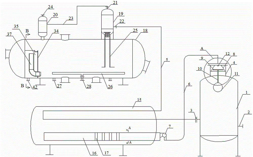
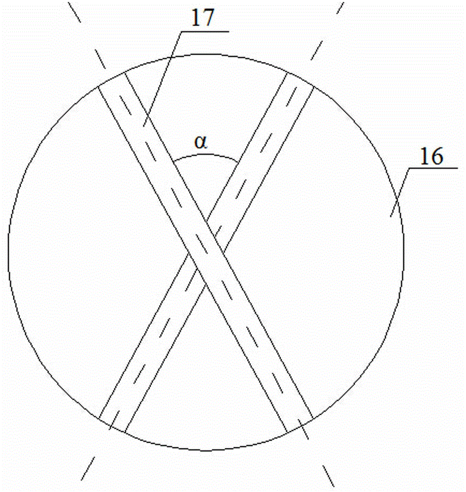
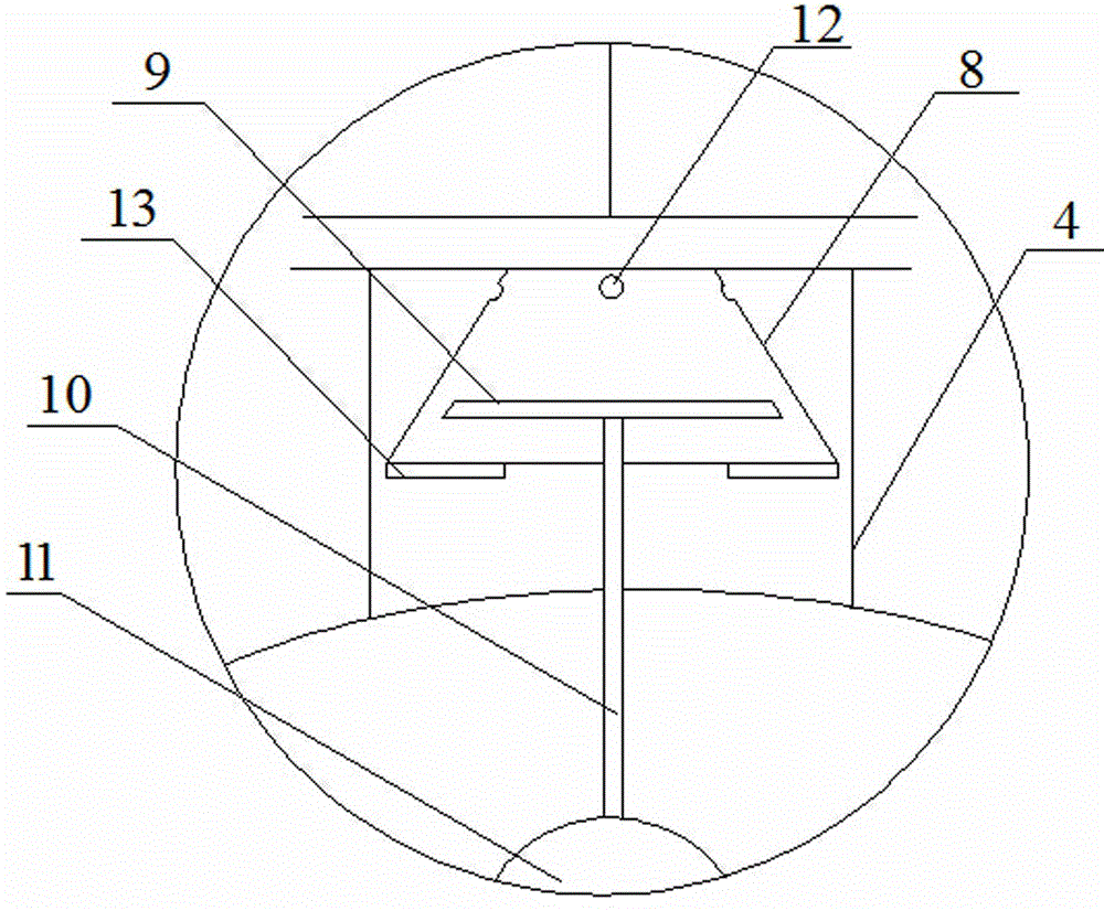
[0029] Such as figure 1 , figure 2 , image 3 , Figure 4 , Figure 7 , Figure 8 , Figure 9 , Figure 10 , Figure 11 and Figure 12 As shown, the crude oil separation system of this embodiment includes a primary separation system and a secondary separation system, and a crude oil heating system is arranged between the primary separation system and the secondary separation system; the primary separation system includes an oil-gas separation system A device 1 is provided with a crude oil inlet 2 and an oil outlet 3 at the bottom of the oil-gas separator, and an anti-overflow non-extinguishing device is provided in the gas outlet 4 at the top of the oil-gas separator, and the oil outlet is connected with an oil pipeline 5, The gas outlet is connected to the natural gas pipeline 6, the oil pipeline is connected to the secondary separation system after being heated by the crude oil heating system, and the natural gas pipeline is connected to the burner 7 arranged on the...


PUM


Abstract

The invention relates to an anti-overflow non-flameout device which can solve the problems that petroleum in an oil-gas separator adopting a heating furnace to provide natural gas is excessive and overflows from a top natural gas pipeline, the natural gas pipeline is blocked by the petroleum and heating of crude oil is affected. The scheme is as follows: the anti-overflow non-flameout device comprises a truncated cone-shaped sleeve which is arranged in the positive direction in a gas outlet at the top end of the oil-gas separator, the outer edge of a small circular surface at the top end of the sleeve is hermetically connected with the inner edge surface of the gas outlet, a gap exists between the outer edge of a large circular surface at the lower end of the sleeve and the inner edge surface of the gas outlet, a blocking piece extending into the truncated cone-shaped sleeve is fixedly arranged on the circumference on the lower end surface of the sleeve, an isolation plate is arranged in the sleeve, the lower end of the isolation plate is connected with a floating ball arranged below the sleeve through a connecting rod, and a plurality of ventilation circular holes are uniformly distributed on the circumference at the top of the side surface of the sleeve. The anti-overflow non-flameout device provided by the invention can prevent a large amount of petroleum from overflowing into other devices from the natural gas pipeline at the upper part of the truncated cone-shaped sleeve, and can ensure that natural gas enters the pipeline from the circular holes at the top of the truncated cone-shaped sleeve so as to ensure the normal operation of production.

Description

technical field [0001] The invention belongs to the field of crude oil separation, in particular to a crude oil separation system. Background technique [0002] In the process of oil storage and transportation separation, crude oil often solidifies due to low temperature, thereby blocking the pipeline, causing high friction and affecting production. In order to solve this problem, heating oil is an effective measure to solve oil solidification. Using heating The oil and gas separator in front of the furnace provides fuel for the heating furnace through pipelines, but the pressure of the oil extracted from the oil production well is unstable. When the pressure is high, the oil and gas separator can be filled quickly, and the outlet of the oil and gas separator cannot be transported outward. Part of the crude oil overflows from the natural gas port with the natural gas, and the natural gas is used as fuel to supply the oil heating equipment-heating furnace through the pipeline...

Claims


Application Information

Patent Timeline
Patent Type & Authority Applications(China)
IPC IPC(8): C10G53/02C10L3/10
CPCC10G53/02C10G2300/1033
Inventor 李东霞徐东海
Owner PUYANG XINGTAI METAL STRUCTURE PROD
Learn More