
Brush manufacturing method and brush manufactured thereby

一种制造方法、刷具的技术,应用在刷具,产业用及/或兴趣用刷具领域,能够解决电势差、金属线断裂、昂贵等问题,达到降低成本、改良机械特性的效果

Inactive Publication Date: 2017-03-01
丹尼尔崔斯佛吕尼
View PDF5 Cites 0 Cited by
  • Summary
  • Abstract
  • Description
  • Claims
  • Application Information

AI Technical Summary

Problems solved by technology

[0035] This can lead to breakage of the metal wire, which makes the resulting brush easy to disintegrate, since the fastening effect created by the plastic mold is quickly destroyed at high temperatures:
[0036] Plastics cannot be used in brushes with special metal components such as stainless steel or non-sparking materials, because they would contaminate the surface, or because of the potential for extreme interactions between the plastic material and the various metal parts that make up the brush. Risk of electric discharge (spark) due to potential difference;
[0037] The different materials in the composition (plastic, steel, paint, etc.) make the recycling of the resulting brushes cumbersome and expensive

Method used


Image

  • Brush manufacturing method and brush manufactured thereby
  • Brush manufacturing method and brush manufactured thereby
  • Brush manufacturing method and brush manufactured thereby

Examples


Embodiment Construction

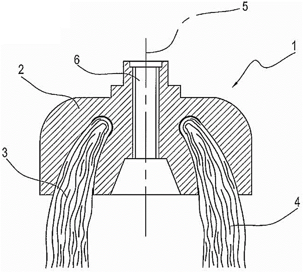
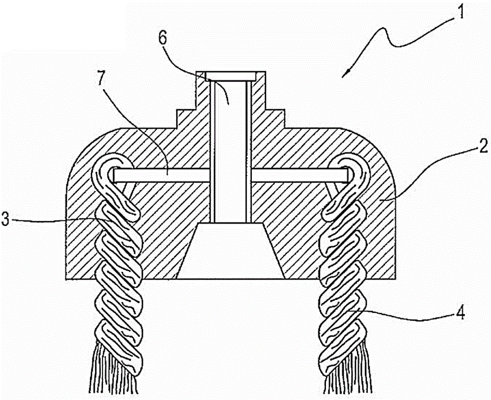
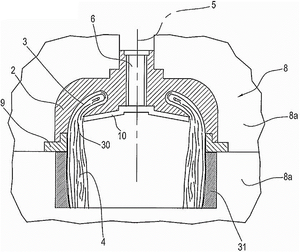
[0128] Referring to the accompanying drawings, number 1 represents the industrial brush tool of the present invention.

[0129] The brush 1 includes a brush body 2 and a plurality of metal wires.

[0130] The wire has a first wire part 3 embedded in the metal brush body 2 and a second wire part 4 for performing a brushing action when said brush 1 (ie brush body 2) rotates on its rotating shaft 5 .

[0131] Initially, the brush body 2 is made of molten metal in which the first wire part 3 of the metal wire is embedded; the bonding metal merges the first wire part 3 so that it is in contact with the brush body 2 firmly combined into a whole.

[0132] The manufacturing method of the above-mentioned brush 1 includes a step of preparing a plurality of metal wires, which are placed in at least one bundle, and the wire bundle has a predetermined width and thus occupies a predetermined space.

[0133] The wire is placed in the cavity of the mold, which has a predetermined geometry, ...


PUM


Abstract

Flanges, outer cups and inner cups with innovative embodiments can also be made with the same molding process, improving the characteristics of the traditional brushes.

Description

technical field [0001] The invention relates to a brush tool manufacturing method and the brush tool manufactured by the method. The present invention is applicable to the field of industrial and / or hobby brushes, that is, brushes that can be used for machining procedures (eg, deburring surfaces, cleaning solder joints, etc.) for industrial or personal use. Background technique [0002] In the conventional brush manufacturing process, the components used to form the brush are generally assembled using a thread restricting device. [0003] These components are the flange, wire loop, and constriction for round brushes, and the inner cup, wire loop, outer cup, and constriction for cup brushes. [0004] In a conventional method, the circular portion of the constriction device is first perforated through the center of the various parts used to form the brush, which are formed by cold compression molding. [0005] The next step is to pull out the edge of the extending portion of...

Claims


Application Information

Patent Timeline
Patent Type & Authority Patents(China)
IPC IPC(8): A46B3/00A46B3/04
CPCA46B3/005A46B3/04A46B2200/3093A46D1/0207A46D1/04
Inventor 丹尼尔·崔斯佛吕尼
Owner 丹尼尔崔斯佛吕尼
Learn More