Pneumatic tire

A technology for pneumatic tires and treads, which is applied to the reinforcement layers, tire parts, and treads of pneumatic tires, can solve the problems of affecting the rolling resistance of tires, affecting the quality of tires, and damaging the fuel consumption performance of vehicles, so as to improve the in-plane torsion. Rigidity, maintaining handling stability, and excellent durability

Active Publication Date: 2015-08-12
SUMITOMO RUBBER IND LTD
View PDF6 Cites 8 Cited by
  • Summary
  • Abstract
  • Description
  • Claims
  • Application Information

AI Technical Summary

Problems solved by technology

Large longitudinal rigidity will not only affect ride comfort, but also increase noise in the frequency domain of 80 to 100 Hz
This tire may impair quietness
And the above-mentioned pressi

Method used


Image

  • Pneumatic tire
  • Pneumatic tire
  • Pneumatic tire

Examples


Example Embodiment

[0107] [Example 1]

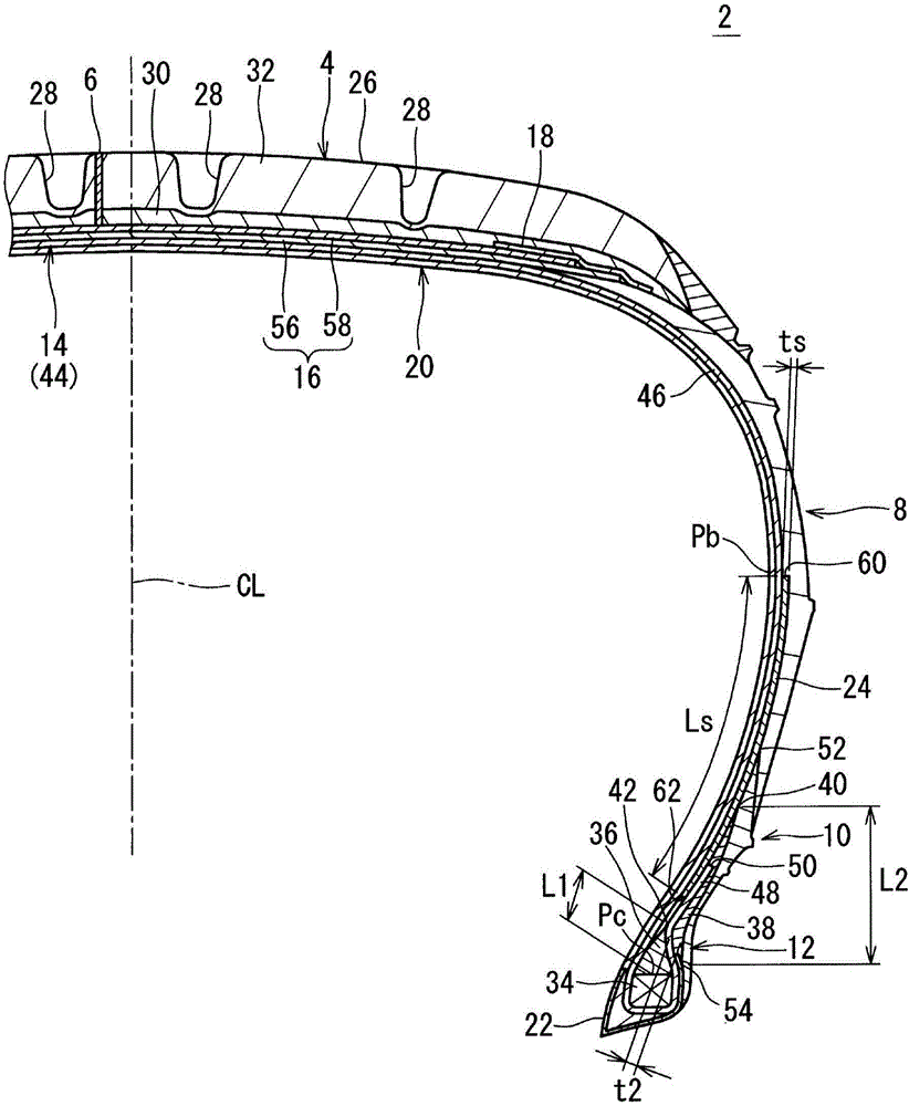
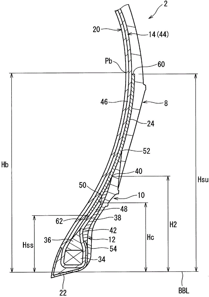
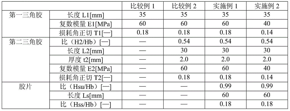
[0108] obtained with figure 1 The pneumatic tire of Example 1 having the basic structure shown and having the specifications shown in Table 1 below. The tire size is 195 / 65R15. The first apex, the second apex, and the film are formed by cross-linking the same rubber component. Therefore, the complex modulus E1 of the first apex, the complex modulus E2 of the second apex, and the complex modulus Es of the film are the same. The loss tangent T1 of the first apex, the loss tangent T2 of the second apex, and the loss tangent Ts of the film are the same.

Example Embodiment

[0113] [Example 2]

[0114] Except changing the rubber composition for the first apex, the second apex and the film and making the complex modulus E1, complex modulus E2 and complex modulus Es and loss tangent T1, loss tangent T2 and loss tangent Ts as follows The tires of Example 2 were obtained in the same manner as in Example 1 except as described in Table 1.

Example Embodiment

[0115] [Example 3-7]

[0116] The tires of Examples 3 to 7 were obtained in the same manner as in Example 1, except that the length L1 of the first apex was as shown in Table 2 below.


PUM

PropertyMeasurementUnit
Complex modulusaaaaaaaaaa
Thicknessaaaaaaaaaa
Thicknessaaaaaaaaaa

Abstract

A pneumatic tire includes a tread, sidewalls, clinches, beads, a carcass, and strips. Each bead includes a core, a first apex and a second apex; the carcass includes a carcass ply which is turned up around the core from the axially inner side toward the outer side, such that it is divided into a main and a turn-up portion; each strip has a radially inner edge positioned between the main and turn-up portions; the second apex is positioned between the turn-up portion and each clinch; each strip has an outer edge in the radial direction positioned to correspond to or on inner side of the point of the tire maximum width; the second apex has an outer edge which is radially inner than the outer edge of each strip, and includes crosslinked rubber having a complex elastic modulus in a range of from 60 to 70 MPa.

Description

technical field [0001] The present invention relates to pneumatic tires. In detail, the present invention relates to a pneumatic tire for a passenger vehicle. Background technique [0002] The tire has a pair of beads. A carcass is erected between the beads on both sides. The bead has a bead core and an apex extending radially outward from the bead core. Usually, the carcass ply constituting the carcass is folded back around the bead core from the inside to the outside in the axial direction. Thus, the main portion and the turned-back portion are formed in the carcass ply. [0003] In the tire, the bead is partially fitted into the rim. In a running state, a large load is applied to the bead portion. Therefore, the durability of the bead portion is very important. Various studies have been conducted on the durability of the bead portion. An example of this research is disclosed in Japanese Patent Laid-Open No. 2005-255047. [0004] Patent Document 1: Japanese Unexam...

Claims


Application Information

Patent Timeline
IPC IPC(8): B60C15/00B60C15/06B60C9/08
CPCB60C2015/061B60C13/02B60C15/0603B60C15/0054B60C15/0607B60C15/0009B60C2015/009B60C2015/0614B60C2015/0617
Inventor 宗泽吾郎
Owner SUMITOMO RUBBER IND LTD
Why Eureka
Try Eureka