Open-end rotor spinning device and method of operating an open-end rotor spinning device

A rotor spinning and free end technology, which is applied in the directions of free end spinning machines, spinning machines, measuring devices, etc., can solve problems such as damage to the spinning rotor bearing device.

Active Publication Date: 2017-05-03
SAURER GERMANY GMBH & CO KG
View PDF7 Cites 0 Cited by
  • Summary
  • Abstract
  • Description
  • Claims
  • Application Information

AI Technical Summary

Problems solved by technology

In addition to detrimental effects on the spinning product, too small a rotor depth can also damage the bearings of the spinning rotor drive

Method used


Image

  • Open-end rotor spinning device and method of operating an open-end rotor spinning device
  • Open-end rotor spinning device and method of operating an open-end rotor spinning device
  • Open-end rotor spinning device and method of operating an open-end rotor spinning device

Examples


Embodiment Construction

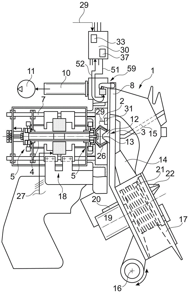
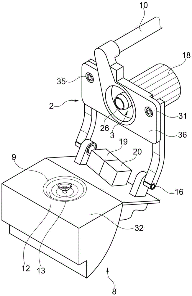
[0031] figure 1 The shown open-end rotor spinning device generally bears the reference numeral 1 and, as usual, has a rotor housing 2 in which a rotor body 26 of a spinning rotor 3 rotates at high rotational speeds.

[0032] The spinning rotor 3 is now driven by an electric motor independent drive, preferably a DC motor 18 , and is mounted with its rotor shaft 4 in the magnetic bearing arrangement 5 . The DC motor 18 is supplied with electrical energy via a line 27 .

[0033] As is known, the rotor housing 2 itself, which is open to the front, is closed during the spinning operation by means of a rotatably mounted cover 8 and is connected to a vacuum source 11 via a corresponding suction line 10, the vacuum The source generates the spinning vacuum required in the rotor housing 2 for yarn production. As can be seen, a channel plate connection 12 is provided in the recess of the cover part 8 , which has a thread delivery nozzle 13 and an opening region of a fiber guide channel...


PUM


Abstract

The invention relates to an open-end rotor spinning device (1) and a method of operating an open-end rotor spinning device comprising a rotor in which a spinning rotor (3) is arranged Cup housing (2) and a pivotable cover (8) for closing the rotor housing (2). According to the invention, a measuring coil (31) and an electrically conductive and / or magnetically permeable measuring element (32) are provided, the measuring coil (31) and the measuring element (32) being arranged in such a way that the rotor housing ( 2) The relative movement between the cover (8) changes the impedance (ZM) of the measuring coil (31) and an analysis device (33) is provided, by means of which it is possible to obtain parameters.

Description

technical field [0001] The invention relates to an open-end rotor spinning device comprising a rotor housing in which a spinning rotor can be arranged and a pivotable cover for closing the rotor housing. The invention also relates to a method for operating an open-end rotor spinning device. Background technique [0002] DE 10 2004 029 020 A1 discloses an open-end rotor spinning device with a rotor housing and a cover. For safety reasons, the rotor housing can only be opened by the maintenance unit or the operator if the spinning rotor is only slowly stalling at a significantly reduced speed. [0003] Furthermore, it must be ensured that the rotor housing is properly closed by the cover when the spinning rotor is restarted. Therefore, before the spinning rotor is restarted, a negative pressure is first applied to the rotor housing. A negative pressure supply must already be present for the spinning operation. The spinning rotor is deflected in rotation by the underpressur...

Claims


Application Information

Patent Timeline
Patent Type & Authority Patents(China)
IPC IPC(8): D01H4/12G01B7/14
CPCG01B21/047G01B11/24D01H4/08D01H13/14
Inventor 努尔-埃丁·巴勒布勒
Owner SAURER GERMANY GMBH & CO KG
Why Eureka
Try Eureka