Speed changer, power transmission system and vehicle

A power transmission system and transmission technology, which is applied in the direction of power devices, vehicle parts, air pressure power devices, etc., can solve the problems of fewer transmission modes, charging modes, single charging path, poor charging efficiency, etc., and achieve the effect of enriching transmission modes

Active Publication Date: 2015-08-19
BYD CO LTD
View PDF5 Cites 1 Cited by
  • Summary
  • Abstract
  • Description
  • Claims
  • Application Information

AI Technical Summary

Problems solved by technology

[0003] However, in the relevant technologies known to the inventor, the transmissions in hybrid vehicles are generally complex in structure, with few transmission modes and low transmission efficiency.
For example, for most hybrid electric vehicles, the charging process is often realized during driving, the charging mode and charging path are relatively single, and the charging efficiency is poor

Method used


Image

  • Speed changer, power transmission system and vehicle
  • Speed changer, power transmission system and vehicle
  • Speed changer, power transmission system and vehicle

Examples


Embodiment 1

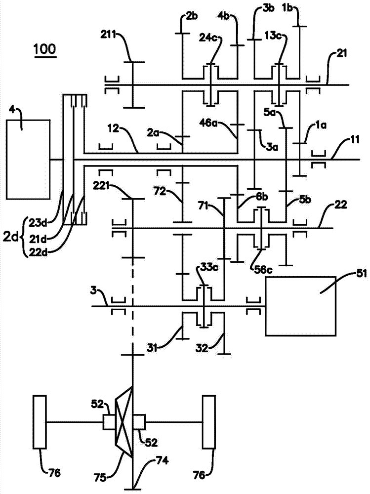
[0120] Such as figure 1 As shown, the engine 4 is connected with the input end 23d of the double clutch 2d, the first output end 21d of the double clutch 2d is connected with the first input shaft 11, the second output end 22d of the double clutch 2d is connected with the second input shaft 12, and the double clutch 2d is connected with the second input shaft 12. The input end 23d of the clutch 2d and the first output end 21d and the second output end 22d of the double clutch 2d can be in disconnected state at the same time, or the input end 23d of the double clutch 2d can be connected with the first output end 21d and the second output end 21d of the double clutch 2d. One of the two output terminals 22d is engaged, or the input terminal 23d of the dual clutch 2d can be simultaneously engaged with the first output terminal 21d and the second output terminal 22d of the dual clutch 2d.

[0121] The second input shaft 12 is a hollow shaft structure, the first input shaft 11 is a ...

Embodiment 2 Embodiment 5

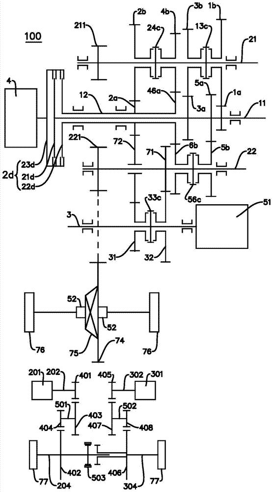
[0177] Such as Figure 2-Figure 5 As shown, the power transmission system 100 and figure 1 The main difference of the power transmission system 100 shown in FIG. The description of the structure will not be repeated here.

Embodiment 6

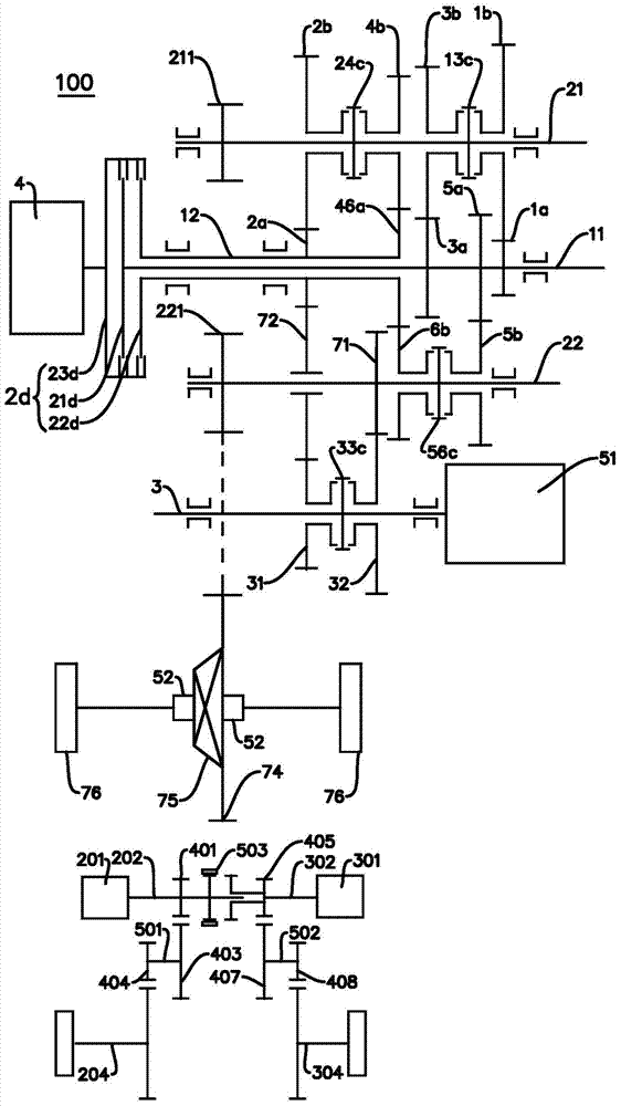
[0179] Such as Figure 6 as shown, Figure 6 The drivetrain 100 shown in the figure 1 The main difference of the power transmission system 100 shown in is the arrangement of the range gear pairs. figure 1 In the embodiment, there are six forward gears, Figure 6 The middle embodiment is five forward gears, Figure 6 On the second output shaft 22 of the embodiment, only one gear driven gear, that is, the fifth gear driven gear 5b is arranged, and the rest of the structures are the same as figure 1 The embodiments are basically the same and will not be repeated here.


PUM


Abstract

The invention discloses a speed changer, a power transmission system and a vehicle. The speed changer comprises a plurality of input shafts, a plurality of output shafts, and a motor driving shaft, wherein a gear-shifting driving gear is arranged on each input shaft; a gear-shifting driven gear is arranged on each output shaft, the gear-shifting driven gears are correspondingly meshed with the gear-shifting driving gears, and a motor gear is arranged on one of the output shafts; a first gear of the motor driving shaft and a second gear of the motor driving shaft sleeve the motor driving shaft in an empty sleeving manner, a motor driving shaft synchronizer positioned between the first gear of the motor driving shaft and the second gear of the motor driving shaft is arranged on the motor driving shaft, the first gear of the motor driving shaft is connected with one of the driving gears in a linkage manner, and the second gear of the motor driving shaft is connected with the motor gear in the linkage manner, Through the adoption of the speed changer disclosed by the invention, the transmission modes are increased, and various working conditions, such as charging electricity during parking, and driving the engine during charging electricity, can be realized.

Description

technical field [0001] The invention relates to the technical field of vehicles, in particular to a transmission, a power transmission system with the transmission, and a vehicle with the power transmission system. Background technique [0002] With the continuous consumption of energy, the development and utilization of new energy vehicles has gradually become a trend. As one of the new energy vehicles, a hybrid vehicle is driven by an engine and / or an electric motor, and has multiple modes, which can improve transmission efficiency and fuel economy. [0003] However, in the relevant technologies known to the inventor, the transmissions in hybrid vehicles generally have complex structures, few transmission modes, and low transmission efficiency. For example, for most hybrid electric vehicles, the charging process is often implemented during driving, the charging mode and charging path are relatively single, and the charging efficiency is poor. Contents of the invention ...

Claims


Application Information

Patent Timeline
Patent Type & Authority Applications(China)
IPC IPC(8): B60K6/36B60K6/54
Inventor 刘静华煜穆金辉
Owner BYD CO LTD
Why Eureka
Try Eureka